Well--after two years of putting it off, waiting for parts, screwing up things left and right... I got the boards done. And of course...like everything else lately, something ain't right.
Sound is distorted. I checked, rechecked and checked again all of my work. I have poured over the schematics looking for clues.
I have nice 15 v from the power supply.
I see 15 volts at the 4 and 8 pins on all opamps (assuming that is what it should be?)
Ribbon cables check out.
I can inject a sine wave which shows up fine at op amp A1. Outputs fine at pin 7 from A1.
Looks good entering op amp A2 at pin 3. But on the output of A2 at pin 1 the signal is already turning to garbage truncating the top and bottom of the sine wave.
I had a spare lm 4562 which I swapped in. Same thing.
I am very much still a beginner at all of this so be kind. I have built several pass diy projects with great success and can read a schematic, have a basic understanding of what the various things are doing--but, definitely not an ee.
I work on projects like this to help me understand this stuff better (which usually works out). But I am now stumped.
Hoping it is something really easy that I am just overlooking but I have tried everything I can think of to troubleshoot and I'm stuck.
I humbly ask for help.
Everything seems to be -15 on pin 4 and +15 on pin 8. I don't think it is a scope issue though I am no expert. If I use the auto feature it still shows a waveform that is clipped. While I don't really understand this circuit I assuming the op amp A2 is connected to the balance pot as the wave form changes when turning the pot. But no matter what comes out distorted.
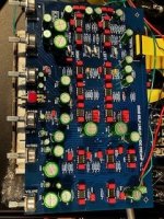
For what it is worth I have attached an image of the pre-amp board.
For what it is worth I have attached an image of the pre-amp board.
Attachments
Yes, in particular the DC at A2a pin 1 is an important clue. Measure it with no signal (input shorted).
Can you post a close up of the scope screen, so we can see the scale settings.
It is important to see whether the signal is clipped (close to the 15V limit), or whether the signal is low and distorted.
Jan
Can you post a close up of the scope screen, so we can see the scale settings.
It is important to see whether the signal is clipped (close to the 15V limit), or whether the signal is low and distorted.
Jan
Thanks for everyone's help. The dc voltage is correct on 4 and 8 getting 15v- and 15v+. On the other pins with no signal there is anywhere from .3 to .6 mv. I will attach an image of the scope on A2a pin1 with no signal. By input shorted do you mean short the inputs at the op amp itself? I did not do that.
Should there be absolutely nothing on those pins without a signal present?
I do have .1uf bypass caps as specified in the bom.
Should there be absolutely nothing on those pins without a signal present?
I do have .1uf bypass caps as specified in the bom.
Attachments
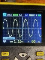
You really have to learn to read a scope. I can't see the hor scale, does it say 5mS or 5uS?
If 5mS, it looks like mains hum, also there's a legend '60Hz' below. Are you in a 60Hz mains country?
So then this is hum, 600mV peak. This is a different issue than the distorted signal you showed before (I think, again, hard to read the scope).
I would disregard this, and focus on the main issue of the distortion.
Shorted input means, shorted input - you'd not just short an opamp input in a circuit.
Can you recreate that scope picture that you showed before with the distorted signal, and note the vertical and horizontal scale?
In the top of the last picture it says: 200mV - that's the vertical scale, voltage per division, and 5mS - the hor scale, 5mS per division.
The reciprocal of the hor scale is frequency.
Jan
Those DC values are fine.Thanks for everyone's help. The dc voltage is correct on 4 and 8 getting 15v- and 15v+. On the other pins with no signal there is anywhere from .3 to .6 mv.
Look at your circuit you attached. You say the signal at pin 3 of A2 is fine. Let's go back to that (recheck it) and also confirm again that pin 1 of A2 is distorted. @jan.didden makes a good point on scope use. Use a decent input level of say 1 volt peak to peak at 1kHz.
Are you using the unbalanced RCA input? If you are then you should have no signal on opamp A1 pins 1, 2 and 3. Check.
With RV1 (balance) turned so the wiper is grounded you should see no signal on pins 6 and 7 of A2b. Check.
Let's see where that gets you
")
The horizontal scale was indeed 5ms and I am in the US so that makes sense that it is a 60hz hum. And for sure, my skills need to improve-just working on this is reminding me of how to read the scope. I just don't use it very often. I'll post a picture of the distorted signal with a 1v 1kh input sine wave in the next comment to Molly.You really have to learn to read a scope. I can't see the hor scale, does it say 5mS or 5uS?
If 5mS, it looks like mains hum, also there's a legend '60Hz' below. Are you in a 60Hz mains country?
So then this is hum, 600mV peak. This is a different issue than the distorted signal you showed before (I think, again, hard to read the scope).
I would disregard this, and focus on the main issue of the distortion.
Shorted input means, shorted input - you'd not just short an opamp input in a circuit.
Can you recreate that scope picture that you showed before with the distorted signal, and note the vertical and horizontal scale?
In the top of the last picture it says: 200mV - that's the vertical scale, voltage per division, and 5mS - the hor scale, 5mS per division.
The reciprocal of the hor scale is frequency.
Jan
Those DC values are fine.
Look at your circuit you attached. You say the signal at pin 3 of A2 is fine. Let's go back to that (recheck it) and also confirm again that pin 1 of A2 is distorted. @jan.didden makes a good point on scope use. Use a decent input level of say 1 volt peak to peak at 1kHz.
Are you using the unbalanced RCA input? If you are then you should have no signal on opamp A1 pins 1, 2 and 3. Check.
With RV1 (balance) turned so the wiper is grounded you should see no signal on pins 6 and 7 of A2b. Check.
Let's see where that gets you
I am currently using the unbalanced in and A1 pin1, 2 and 3 have no signal.
With RV1 turned there is no signal at 6 and 7 of A2b
Here are some updated pictures hopefully more clear with descriptions
1v 1khz signal going into pin 5 of a1b---this remains the same at the output, pin 7 of a1b
signal at pin3 of A2
signal at pin1 of a2-----is it supposed to do this?
Last is signaificant. Is there DC at that pin? Measure DC with input set to zero.I am currently using the unbalanced in and A1 pin1, 2 and 3 have no signal.
With RV1 turned there is no signal at 6 and 7 of A2b
Here are some updated pictures hopefully more clear with descriptions
1v 1khz signal going into pin 5 of a1b---this remains the same at the output, pin 7 of a1b
View attachment 1106499
signal at pin3 of A2
View attachment 1106500
signal at pin1 of a2-----is it supposed to do this?
View attachment 1106501
To try to isolate the cause, can you remove opamps A3, A4 and A5 (assuming they are on a socket?), how does the signal look then?
Also, the -15 at pin 4 of A2 - did you measure that at the actual pin on the opamp body? Absence of that would explain this too.
Jan
Last edited:
At this point I would go with Jan's suspicion of a missing rail causing that severe negative clipping. Measure on the pin itself.
If that turns out to be OK then we are looking for something really odd. Could there be a short to 'something' on the output side of caps C5 and C8? Something that behaves like a diode. You could try lifting one end of C8 and then C5 and seeing if the signal is then normal on pin1
If that turns out to be OK then we are looking for something really odd. Could there be a short to 'something' on the output side of caps C5 and C8? Something that behaves like a diode. You could try lifting one end of C8 and then C5 and seeing if the signal is then normal on pin1
- Home
- Source & Line
- Analog Line Level
- Doug Self Preamp from Linear Audio #5