Hello everyone!
I am newbie in layout design but after making two single cards of this assembly to the superb sound, I decided to design a stereo layout.
This layout will include a power supply and volume potentiometer to the minimum but already proposed suggestions are already planned.
All help will be welcome!
Kuartlotron thread:
http://www.diyaudio.com/forums/anal...kens-simple-error-correction-superbuffer.html
Last edited:
Yeah that is better but still either one of the sets (inputs/outputs or both) could be at the backside of the board. I mean the side that is closest to the RCA plugs. that way wiring will be easy and it will look better. I see you implemented a motorized potentiometer. Nice. Add the pads for RK27 also. Pads cost nothing and they give the builder the opportunity to choose between RK27 and a motorized potentiometer. Just use two footprints over each other.
Last edited:
YES ! Excellent. This way mounting it in a case will be easy just like wiring the RCA's. Always think of how it will look and feel when in a case and how you are going to install a board. For world peace please include M3 mounting holes too (one at every edge). The potentiometer must be aligned to the upper side of the board to be able to mount it flush with the front cover of your case and to be able to tighten it with its nut....i.e. lower side of the bushing must be on the green line. It will free board pace so that you can add CLC filtering of the power supply + and -. Coils are our friends.
Pads for optional input/output caps ? Muting relay (can be just above the output connectors, a very small relay is enough) ? A few more hours and I'll be buying a board from you")
Pads for optional input/output caps ? Muting relay (can be just above the output connectors, a very small relay is enough) ? A few more hours and I'll be buying a board from you
Last edited:
For RK27 I must draw the footprint because at first I did not plan a motorized potentiometer but it is a good idea.
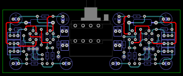
It's not very well arranged and not to scale but I propose this provision and when it will be good to you after I put the other components.
It's not very well arranged and not to scale but I propose this provision and when it will be good to you after I put the other components.
Attachments
The motor case should be grounded. A PCB in my junk pile has a motorized pot bypassed by a 22nF ceramic and driven by a TA7291:
http://www.toshiba.com/taec/components2/Datasheet_Sync/200706/DST_TA7291P-TDE_EN_3604.pdf
I think the ceramic cap would be damped nicely by the saturated junctions of the bridge driver.
http://www.toshiba.com/taec/components2/Datasheet_Sync/200706/DST_TA7291P-TDE_EN_3604.pdf
I think the ceramic cap would be damped nicely by the saturated junctions of the bridge driver.
AndrewT:
It is noted, thank you!
Kentoken:
Yes, it's expected and all will be well used when I have designed the footprint RK27 for positioning components.
@Jean Paul
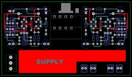
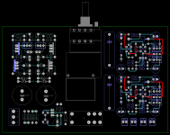
Here is my investment proposal on the card. For the power part I adopted a circuit with conventional LM 317/337 preceded by a pre-regulation, which gives an excellent result.
Regard's!
It is noted, thank you!
Kentoken:
Yes, it's expected and all will be well used when I have designed the footprint RK27 for positioning components.
@Jean Paul
Here is my investment proposal on the card. For the power part I adopted a circuit with conventional LM 317/337 preceded by a pre-regulation, which gives an excellent result.
Regard's!
Attachments
Hi I would place the PSU next to the rectifier diodes (keep PSU parts grouped together).
- Try to keep a sound distance between AC input and the buffers inputs and outputs just in case.
- Move rectifier and diodes 10 mm closer to the corner but leave enough space for 3 mm mounting holes with clearance for your screw driver
- Inputs and outputs can go to the right section.
- You could add pads for smaller input caps too. Just put the footprint over the existing one. Smaller caps pick up garbage less easy.
- Output caps will be possibly somewhat larger when you choose MKP caps due to their value. Still 10 µF MKT/MKS caps exist in 5 mm and 10 mm pitch.
I use Wima MKS 2-XL and ERO green MKT a lot and they sound just good. Of course we could discuss for pages that MKP is better etc. but in this case I think smaller caps will perform better certainly with the motorized potentiometer in the vicinity. A ground plane might be a wise idea too.
Placing the potentiometer like you did now will be way better when mounting the board against the front cover. Thanks. I sent you a PM.
Last edited:
OK, I'll adapted all this (sorry but I am novice in layout design ).
For the cicuit of mutting I thought implement the scheme by Rod Elliott but I do not know if it is "legal".
Project 104 - Preamp/ crossover muting circuit
).For the cicuit of mutting I thought implement the scheme by Rod Elliott but I do not know if it is "legal".
Project 104 - Preamp/ crossover muting circuit
Copying from Rod Elliott is possibly not allowed as Rod lives from his electronics company. Of course you can ask him if it's OK, he is a nice chap. Maybe he does not object at all. You could use the circuit of the Mezmerize. It is simple and effective and textbook standard, no worries if you use that one I think. It might be possible to squeeze in the motor driver circuit and IR control too...
Just thought your PCB develops quite fast. Maybe it is wise to have a separate thread for your design ? It IS Keantokens thread after all. If he does not object we can go on. It happens more often that more PCB versions exist of one design. It could however be that it interferes with the other things going on in this thread. Just being cautious.
Just thought your PCB develops quite fast. Maybe it is wise to have a separate thread for your design ? It IS Keantokens thread after all. If he does not object we can go on. It happens more often that more PCB versions exist of one design. It could however be that it interferes with the other things going on in this thread. Just being cautious.
Last edited:
Yes you are right, I had not thought about that. I open a thread on this design.s quite fast. Maybe it is wise to have a separate thread for your design ? It IS Keantokens thread after all. If he does not object we can go on. It happens more often that more PCB versions exist of one design. It could however be that it interferes with the other things going on in this thread. Just being cautious.
Sorry Keantoken!
Wintermute thank you, that's cool!and it has been done, with a little jiggery pokery to get the first post to be the first... not chronologically accurate but sets the stage.

I kept the old sets of investment proposals and I suggest those above.
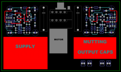
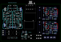
I have grouped sets supply, buffers and add part mute. It is possible to do this tour with my Borbely-Sulzer supply that has a soft-start but the presence of many components is required.
PS: the footprint of the potentiometer is not Conform, it's just to see the investments.
Regard's!
I have grouped sets supply, buffers and add part mute. It is possible to do this tour with my Borbely-Sulzer supply that has a soft-start but the presence of many components is required.
PS: the footprint of the potentiometer is not Conform, it's just to see the investments.
Regard's!
Attachments
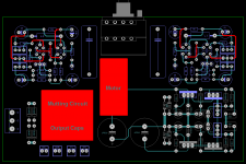
You can use a much smaller relay. It only shorts the outputs at power on/off. You can use low power type signal/telecom relays. This board looks a good start. You could think of input control with relays too. Routing the input signals will be a hard one I guess. If you are determined to keep the potentiometer in the middle of the board thing might be difficult. If you can move the potentiometer to the right and move the buffers to the middle things become more easy again.
Last edited:
Ok, I'll see everything ca.You can use a much smaller relay. It only shorts the outputs at power on/off. You can use low power type signal/telecom relays. This board looks a good start. You could think of input control with relays too. Routing the input signals will be a hard one I guess. If you are determined to keep the potentiometer in the middle of the board thing might be difficult. If you can move the potentiometer to the right and move the buffers to the middle things become more easy again.
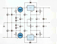
A question about the supply.
According to you the Borbely-Sulzer is it sensible or simply that of the following diagram (a listening I did not notice any difference between the two).
With this one I win instead.
Attachments
- Status
- This old topic is closed. If you want to reopen this topic, contact a moderator using the "Report Post" button.
- Home
- Source & Line
- Analog Line Level
- The Kuartlotron - All in one layout conception