This is not a problem!Routing the input signals will be a hard one I guess. If you are determined to keep the potentiometer in the middle of the board thing might be difficult.

Attachments
I saw it too late!
I've used this small relay, I think it is appropriate.
https://www.reichelt.de/Miniature-R...92&ARTICLE=79353&START=0&SORT=artnr&OFFSET=16
One relay on inputs and one relay on outputs?You can use a much smaller relay.
You could think of input control with relays too.
I've used this small relay, I think it is appropriate.
https://www.reichelt.de/Miniature-R...92&ARTICLE=79353&START=0&SORT=artnr&OFFSET=16
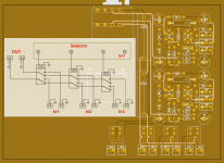
OK. That relay seems OK for the purpose. I meant if you want 4 or 5 inputs you could add 4 or 5 relays for choosing CD/AUX/TUNER/TV/MEDIA etc. Not necessary if you use a rotary switch with cabling but otherwise it is a very healthy way of choosing inputs. You operate the relays with a rotary switch or remote control. It makes the layout more complex but it enhances ease of installation/operation but it is not a definite must.
Last edited:
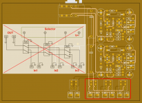
No that won't work. Just look at how they are connected ! Please compare to the schematic here to see what's wrong:
http://rstaudio.de/AlephP/Input.pdf
http://rstaudio.de/AlephP/Input.pdf
Last edited:
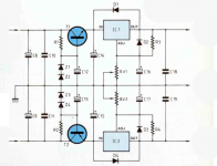
I hesitate to suggest this but if you have the opportunity, perhaps you might like to try the first power reg circuit but with the simpler zener ref buffer (Q1, Q2, etc) on the output like a simplified "Teddy Reg"
On the relay selector design, many designs do just like you have outlined and occasionally will someone remember that when 2 or more sources (for example) are plugged in, their separate earthing systems are also connected rogether with sometimes severe problems - one way around this is to add 3 more relays just to add/select the associated ground wire with the signal wire - there's plenty of room and with optional links for possible connection - just an option, not necessarily a design protocol
Perhaps add provision for diodes & snubbers across the relay coils and keep any relay power tracks isolated from any ground plane, etc ...
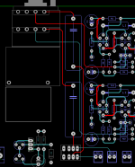
Maybe reduce the lengths of those tracks when appropriate - the pot doesn't necessarily have to be on the edge of the pcb, for example ...
On the relay selector design, many designs do just like you have outlined and occasionally will someone remember that when 2 or more sources (for example) are plugged in, their separate earthing systems are also connected rogether with sometimes severe problems - one way around this is to add 3 more relays just to add/select the associated ground wire with the signal wire - there's plenty of room and with optional links for possible connection - just an option, not necessarily a design protocol
Perhaps add provision for diodes & snubbers across the relay coils and keep any relay power tracks isolated from any ground plane, etc ...
Maybe reduce the lengths of those tracks when appropriate - the pot doesn't necessarily have to be on the edge of the pcb, for example ...
Switching GND too will give more problems than it solves in many cases. Ground loops manifest themselves when every device has a direct connection to PE. A solution is to only connect the GND of the power amp to PE and keep the GND of all other devices floating. This works.
The relays must have an antiparallel diode over their coils.
The relays must have an antiparallel diode over their coils.
Check that the Signal Return/Ground plane is actually under every Signal Flow route for the WHOLE length of that route for EVERY Signal. Make sure there are no cuts across the ground where a signal passes over.
Separate the dirty Power Ground from the clean Signal Return Ground.
Separate the dirty Power Ground from the clean Signal Return Ground.
No that won't work. Just look at how they are connected ! Please compare to the schematic here to see what's wrong:
http://rstaudio.de/AlephP/Input.pdf
On my schema is not good
but on the printed circuit it is correct it seems!The coil diodes on the go ries.
Attachments
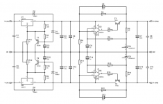
To avoid clicks and plops better reference the inputs to GND with a high value resistor like 475kOhm. Before the relay contacts that is. Sometimes not a necessity but it is good design practice anyway. I would also use an RC filter at the input (after the input cap) so just a series resistor and a cap to GND per channel to filter out RF/HF.
Please try not to cross input and output tracks. If you implement a GND plane it will not be a problem.
Please try not to cross input and output tracks. If you implement a GND plane it will not be a problem.
Last edited:
OK, I'll see that.
Before continuing to route my circuit (it's work, pfff!) And add your recommendations, I want to know if it's ok like that with the resistors. The supply of the coils is not shown.
For the coils diodes, 1n4148 can work?
PS: sorry for my not very clear schematic!
Before continuing to route my circuit (it's work, pfff!
) And add your recommendations, I want to know if it's ok like that with the resistors. The supply of the coils is not shown.For the coils diodes, 1n4148 can work?
PS: sorry for my not very clear schematic!
Attachments
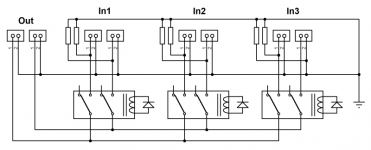
I'm getting old!In3 has one of the connectors swapped.
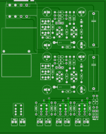
I have changed a bit the general layout and add the filter R / C (1K / 680pF).
Questions:
For the diodes on relays, 1N4148 appropriate or requires 1N4001?
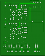
A ground plane or no ground plane?
If a ground plane, above or below?
Thank you!
Attachments
1N4148 will be fine because the freewheel current cannot exceed the DC coil current.
With those traces breaking the plane, it will not be so much a plane as a shield. That may still help. If you do it, then don't connect the plane to anything except for output signal ground.
With those traces breaking the plane, it will not be so much a plane as a shield. That may still help. If you do it, then don't connect the plane to anything except for output signal ground.
Last edited:

Input filter is R first then C to GND...
You know what they say about inputs. If you think you will need 3 you will need a 4th input the next day Just kidding, most will be able to live with 3 inputs.
Please add M3 mounting holes. It will make installation simpler and the device will be more sturdy.
No one said it was easy
You know what they say about inputs. If you think you will need 3 you will need a 4th input the next day
Just kidding, most will be able to live with 3 inputs.Please add M3 mounting holes. It will make installation simpler and the device will be more sturdy.
With this small Kuartlotron it is not easy!
No one said it was easy
Last edited:
- Status
- This old topic is closed. If you want to reopen this topic, contact a moderator using the "Report Post" button.
- Home
- Source & Line
- Analog Line Level
- The Kuartlotron - All in one layout conception