I can do a group buy for the PCBs if there is enough interest. BPPBP is a relatively small PCB at 140x49mm, and depending on the quantity, the cost of one PCB can be around $10 including shipping to continental U.S., or slightly more if we go for fancy colors and ENIG finish. Unfortunately, shipping elsewhere (Europe) will add $15 per package.
Also - if Hans agrees - it would be nice to combine BPPBP board with his relay volume control.
Do you think there would be interest? The project has been around for a while, and thanks to Jan Didden and Linear Audio, the boards and completed builds have been available.
Here is everything you would need for the manual and the remote volume control, as well as the 4 input extension. Dropbox - Zipped - Simplify your life
Do with it as you like.
Succes,
Hans
Group Buy thread created
Thank you Hans!
I just created the GB thread here. Let us see what kind of interest it generates.
Thank you Hans!
I just created the GB thread here. Let us see what kind of interest it generates.
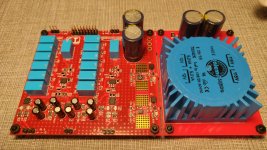
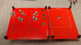
After a lot of sweat and swearing we just finished and tested our interpretation of the circuit using OPA1612/OPA2192, 6 relays per channel with attenuation from 0-63dB in 1dB steps and LT3042/LT3093 regulators. Boards have 4 layers.
More information here: Balanced Stepped Volume Control
Schematics and PCB files are available on gitlab: Files * master * Jurgen Herrmann / VolCtrlDR * GitLab
I quick note on the attenuator resistors. There's a python script on gitlab which I used to simulate all possible resistor combinations in the E-series to get away with the least possible deviation from the desired 1/2/4/8/16/32dB steps. The 16 and 32 dB steps are even combined by using two resistors in parallel to fine tune them. On paper the resulting precision using 0.1% resistors is astonishing! First measurements seem to fully back this...
A controller using a 5" oled touchscreen, a ASUS tinker board, a lot of relay drivers, power good monitoring, i2c DAC controls, HTTP remote control etc... will be available soon. Of course all the software and hardware will be open source too.
Have fun with it... So did we today testing and measuring the circuit")
PS: Here's the output from the resistor calculation script:
More information here: Balanced Stepped Volume Control
Schematics and PCB files are available on gitlab: Files * master * Jurgen Herrmann / VolCtrlDR * GitLab
I quick note on the attenuator resistors. There's a python script on gitlab which I used to simulate all possible resistor combinations in the E-series to get away with the least possible deviation from the desired 1/2/4/8/16/32dB steps. The 16 and 32 dB steps are even combined by using two resistors in parallel to fine tune them. On paper the resulting precision using 0.1% resistors is astonishing! First measurements seem to fully back this...
A controller using a 5" oled touchscreen, a ASUS tinker board, a lot of relay drivers, power good monitoring, i2c DAC controls, HTTP remote control etc... will be available soon. Of course all the software and hardware will be open source too.
Have fun with it... So did we today testing and measuring the circuit
PS: Here's the output from the resistor calculation script:
Code:
running simulation for Rin = 806, 825, 844, 866, 886, 909, 931, 952, 976, 1000, 1020, 1050, 1070, 1100, 1130, 1150, 1180, 1210, 1240, 1270, 1300, 1330, 1370, 1400, 1430, 1470, 1500, 1540, 1580, 1620, 1650, 1690, 1740, 1780, 1820, 1870, 1910, 1960, 2000, 2050, 2100, 2150, 2210, 2260, 2320, 2370, 2430, 2490, 2550, 2610, 2670, 2740, 2800, 2870, 2940, 3010, 3090, 3160, 3240, 3320, 3400, 3480, 3570, 3650, 3740, 3830, 3920,  Simulation done.

Found result:
  Rin:   887.00
  R01:    96.46 ->     97.6
  R02:  7269.39 ->   7320.0
  Actual attenuation: -1.010dB (-1.009dB/-1.011dB, deviation: 0.002dB)
  R03:   182.43 ->    182.0
  R04:  3425.70 ->   3400.0
  Actual attenuation: -1.999dB (-1.996dB/-2.001dB, deviation: 0.004dB)
  R05:   327.34 ->    324.0
  R06:  1516.52 ->   1500.0
  Actual attenuation: -3.980dB (-3.976dB/-3.985dB, deviation: 0.009dB)
  R07:   533.88 ->    536.0
  R08:   586.68 ->    590.0
  Actual attenuation: -8.003dB (-7.995dB/-8.011dB, deviation: 0.017dB)
  R09:   746.42 ->    750.0
  R10:   167.06 ->    169.0
  !!! R09 consists of 768.0 and 40200.0 in parallel.
  Actual attenuation: -15.999dB (-15.985dB/-16.012dB, deviation: 0.027dB)
  R11:   864.72 ->    866.0
  R12:    22.85 ->     22.6
  !!! R11 consists of 887.0 and 23700.0 in parallel.
  Actual attenuation: -31.997dB (-31.980dB/-32.013dB, deviation: 0.033dB)
Absolute worst case summed deviation between two channels: 0.092dB
Attachments
Last edited:
Nice resultsAfter a lot of sweat and swearing we just finished and tested our interpretation of the circuit using OPA1612/OPA2192, 6 relays per channel with attenuation from 0-63dB in 1dB steps and LT3042/LT3093 regulators. Boards have 4 layers.
More information here: Balanced Stepped Volume Control
Schematics and PCB files are available on gitlab: Files * master * Jurgen Herrmann / VolCtrlDR * GitLab
I quick note on the attenuator resistors. There's a python script on gitlab which I used to simulate all possible resistor combinations in the E-series to get away with the least possible deviation from the desired 1/2/4/8/16/32dB steps. The 16 and 32 dB steps are even combined by using two resistors in parallel to fine tune them. On paper the resulting precision using 0.1% resistors is astonishing! First measurements seem to fully back this...
A controller using a 5" oled touchscreen, a ASUS tinker board, a lot of relay drivers, power good monitoring, i2c DAC controls, HTTP remote control etc... will be available soon. Of course all the software and hardware will be open source too.
Have fun with it... So did we today testing and measuring the circuit
PS: Here's the output from the resistor calculation script:
Code:running simulation for Rin = 806, 825, 844, 866, 886, 909, 931, 952, 976, 1000, 1020, 1050, 1070, 1100, 1130, 1150, 1180, 1210, 1240, 1270, 1300, 1330, 1370, 1400, 1430, 1470, 1500, 1540, 1580, 1620, 1650, 1690, 1740, 1780, 1820, 1870, 1910, 1960, 2000, 2050, 2100, 2150, 2210, 2260, 2320, 2370, 2430, 2490, 2550, 2610, 2670, 2740, 2800, 2870, 2940, 3010, 3090, 3160, 3240, 3320, 3400, 3480, 3570, 3650, 3740, 3830, 3920, Simulation done. Found result: Rin: 887.00 R01: 96.46 -> 97.6 R02: 7269.39 -> 7320.0 Actual attenuation: -1.010dB (-1.009dB/-1.011dB, deviation: 0.002dB) R03: 182.43 -> 182.0 R04: 3425.70 -> 3400.0 Actual attenuation: -1.999dB (-1.996dB/-2.001dB, deviation: 0.004dB) R05: 327.34 -> 324.0 R06: 1516.52 -> 1500.0 Actual attenuation: -3.980dB (-3.976dB/-3.985dB, deviation: 0.009dB) R07: 533.88 -> 536.0 R08: 586.68 -> 590.0 Actual attenuation: -8.003dB (-7.995dB/-8.011dB, deviation: 0.017dB) R09: 746.42 -> 750.0 R10: 167.06 -> 169.0 !!! R09 consists of 768.0 and 40200.0 in parallel. Actual attenuation: -15.999dB (-15.985dB/-16.012dB, deviation: 0.027dB) R11: 864.72 -> 866.0 R12: 22.85 -> 22.6 !!! R11 consists of 887.0 and 23700.0 in parallel. Actual attenuation: -31.997dB (-31.980dB/-32.013dB, deviation: 0.033dB) Absolute worst case summed deviation between two channels: 0.092dB

Congratulations! Great job! 
My two cents:
1) It is smart to vary Rin to minimize deviations. One can also vary attenuation step - it is a volume control, not a measurement rig, so 1.1dB or 0.9dB may be acceptable instead of 1dB. With that you can improve deviations even further. You can also obtain very good precision even with E24 resistor values (which would of course still need close tolerances).
2) When simulating, Rin that an upstream stage sees will depend on the downstream stages that are engaged. Ideally, Rin is constant, but with actual E-series resistor values, Rin and hence the attenuation will vary somewhat. This is a little tricky to simulate in Excel but should be trivial in your Python script.
3) The attenuator's output impedance seen by the U3A/U8A is variable, which will increase distortion, particularly at higher frequencies; this problem was mentioned by BP in his original article and is related to the non-linearity of input impedance (in particular input capacitance) of the opamp. There is also a (long) paper with experimental measurements; it is in Russian but Google Translate does an adequate job translating it. The author also discusses ways to minimize that extra distortion, including opamp rolling and optimizing resistor values.
4) With L-pad attenuator(s) in between, the connections U3B->U3A and U8B->U8A are not balanced and, in principle, more likely to pick up interference then a balanced connection. Unfortunately, there seems not to be a better way to use L-pads with balanced connection.
Last edited:
About your comments:
1) We plan to use these for a three way and a five way active project, where some ways might have more attenuation than others, so for us it had to be equal steps all the way. But for a stereo board you'r right of course. In the end after simulation all the values the tolerances were way down even with 1dB steps. And precision resistors tend to be available in finer grained series anyways. But the script can be modified to use different E-series anyways.
2) this was the point in the first place to use a python script, the attenuator now always has "Rin" as input and output impedance, no matter what.
3) As mentioned in 2) - output impedance is always 887 Ohms in our case and operates into a virtual ground at the negative input of the following opamp, so I thought that this point was covered also?!
4) That's correct. After all, engineering is always an art of choosing sensible, workable solutions. At least I tried to keep the area of the attenuator as small as possible. We did some measurements with a EMU 404 and 50Hz hum was down at ~4-5dB above the noise floor of the soundcard, don't remember the exact value. Good enough IMHO especially considering that the mains transformer was still attached to the audio pcb and thus very near.
What I had in mind are all equal steps, but each step is not 1dB but, say, 1.1dB. Then you get stages with 1.1, 2.2, 4.4, 8.8, 17.6, 35.2 dB attenuation and, hopefully, a better fit between ideal resistor values and E-series values. But you're right, using E96 precision resistors makes this a moot point.for us it had to be equal steps all the way
One cannot have it both ways with L-pads. If the input impedance is constant (as is in your case), the output impedance varies, much like that of a potentiometer. For instance, at -32dB, the output impedance is 22.6||887||23700 = 22ohm, while at -8dB it is 590||536=280ohm. Thinking about it, these are low impedances, and they are in series with 887 ohm, so it should not be a practical issue.the attenuator now always has "Rin" as input and output impedance.
If you had non-inverting input grounded, the inverting input would be the virtual ground, and the input capacitance of the opamp would see zero voltage. If both inputs see some source impedance, there is some (variable) common voltage, and the impedance for the inverting and non-inverting inputs must be equal in order for the input currents to cancel. But again, with the low impedances that you have, this should not be a practical problem.operates into a virtual ground at the negative input of the following opamp
So did I...tried hard to come up with a switched resistor solution in the negative feedback path which is dB-linear but failed miserably
Could not agree more!engineering is always an art of choosing sensible, workable solutions
As I said, great job! Thank you for publishing the design. It would be interesting to see your controller.
What I had in mind are all equal steps, but each step is not 1dB but, say, 1.1dB. Then you get stages with 1.1, 2.2, 4.4, 8.8, 17.6, 35.2 dB attenuation and, hopefully, a better fit between ideal resistor values and E-series values. But you're right, using E96 precision resistors makes this a moot point.
You can actually do that as the python script accepts a list of attenuation steps.
Thanks very much for the clarification about the input impedance the opamp sees. now i finally think I have understood the issue! We'll hopefully see/hear it soon how it sounds.
As I said, great job! Thank you for publishing the design. It would be interesting to see your controller.
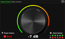
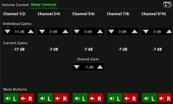
Thanks, very much appreciated! The controller will be a real beast, probably not very useable for a lot of people. The design goals are vast. We need to control up to five volume control boards, so 35 relay outputs and 10 power good inputs, up to 10 mono PAs with a mute relay each and pos/neg power good signal and dc detection and up to 5 stereo dac boards with power good signal each and i2c programming capability. I would think that this is way too much effort for a lot of people out there... Also using a tinker board as controller cpu might seem overkill but using standard linux I whipped up the GUI with a fancy control knob in no time, also giving access to per way attenuation etc. The remote controlling capabilities include HTTP and for more detailed control one can use vnc which is rather nice. I attached screenshots of the current GUI state. The tab for the DAC controls is still missing as no dac boards were designed yet.
Once the controller is finished I will probably announce this whole project in it's own thread. Sorry for almost hijacking this one
Attachments
If you had non-inverting input grounded, the inverting input would be the virtual ground, and the input capacitance of the opamp would see zero voltage. If both inputs see some source impedance, there is some (variable) common voltage, and the impedance for the inverting and non-inverting inputs must be equal in order for the input currents to cancel.
One more question on that topic: If I see the circuit correctly in case of using it for balanced output the noninverting input terminal of the output opamp is grounded via a resistor. Why not omit this one in this case and directly ground it? Wouldn't that be better then?
One more question on that topic: If I see the circuit correctly in case of using it for balanced output the noninverting input terminal of the output opamp is grounded via a resistor. Why not omit this one in this case and directly ground it? Wouldn't that be better then?
Better in what way ?
The last op-amp, configured as level shifter in your circuit diagram, produces a perfect hot output signal with reference to either the Balanced or the SE cold signal at the output socket.
That is with the restriction that the PCB layout correctly supports this.
Hans
Better in the way that I can get rid of the unmatched input impedances on the +/- terminals of the output opamp. But i think I can see the catch now, if the + input was connected to GND the output circuitry would loose the ability to reference the "cold" signal and instead would be referenced to GND and that's not what we want. Sorry for the possibly silly questions, still learning here...
Oh, and one last remark.
I don’t understand the two options for the level shift resistor.
When just using one, you could place a short circuit strap next to the 22R enabling to switch between Balanced and SE.
This will make the layout much more straightforward with hot and cold neatly going together in parallel up to the output sockets, signal and return together being less sensitive to EMI pollution.
Hans
IF I am correct the inference is that the proposed PCB differs from the original as was available via the Linear Audio boards, then I will wait until the circuitry has been finalised. The proposal for an extra input however is acceptable. I am leaving my name on the 'interested' list until the actual circuit has been established. However I shall withdraw if my fears are realised.
Hi - have you made any progress with the input board+volume controller with your Arduino?I have a few of his Input controller boards too. Still working out the details on getting them working with the arduino. I'm having issues with the rotary encoder pushbutton code, to control everything via one control. I may just go back to using a selector switch and an I2C chip..
Would you mind sharing your modified code with us?
I've tried half a dozen pots started with the bom part, tried khozmo ladder and shunt stepped pots, ended up with a tkd 601. Which is better than all of them. Less hassle than the rc Khozmo pots which all ended up picking up noise and better channel balance than any other pot I tried, 1% across the full range.
Did you consider the maya solution?
I've tried half a dozen pots started with the bom part, tried khozmo ladder and shunt stepped pots, ended up with a tkd 601. Which is better than all of them. Less hassle than the rc Khozmo pots which all ended up picking up noise and better channel balance than any other pot I tried, 1% across the full range.
... and further, have you done anything about the usefulness of the travel of the pot?
I do have the Maya to implement but also looking to make a simple version.. but still immune from user error.. I might have to come up with a mechanical solution to turning the pot within a good range.
- Home
- Source & Line
- Analog Line Level
- BPPBP - Bruno Putzey's Purist Balanced Preamp (well a balanced volume control really)