Quick question for you gents.
My BPBP worked fine on a +/-/0v 15 volt feed, then I cased it all up and now the positive reg doesn't light up with the same dc feed, but it works fine on a +12/0v-12v a.c. feed.
Any suggestions before I crack her open. All connection via same 3 pin terminal block. I've tried all possible dc+12v input options on that 3 pin block and none work.
I'd think a fried rectifier but they must work as they rectify the a.c....
Weird huh.
a +/-/0v 15 ... +12/0v-12v a.c. feed.
Is the different order on the above voltage series just sloppy writing or is that really different? If the latter, that may explain it maybe?
Jan
I am using the BOM linked on this page
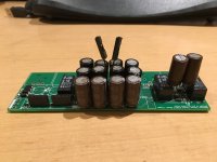
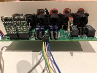
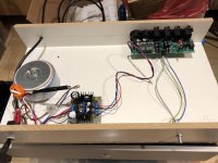
One more caveat with this BOM: after ordering from Mouser I found that some of the caps are larger than intended (see pic). I must have missed something, but the part numbers are the same or very similar.
Attachments
Last edited:
One more caveat with this BOM: after ordering from Mouser I found that some of the caps are larger than intended (see pic). I must have missed something, but the part numbers are the same or very similar.
Ah... Unfortunately, one always needs to check through the thread to double check no problems with the BOM. A shame it wasn't updated!
When I ordered my parts (I used the list and recommendations in the original thread), I also double checked the size and pitch before ordering.. There was a problem with the original BOM too I seem to remember but people's own discoveries warned future DIYers.. Picking out capacitors can be a real pain when you have to juggle so many paramaters! Always puts me off ordering parts.
Here is a correction to it: Bruno Putzeys Balanced Preamp - Group Buy Part 3, Page 17
Last edited:
Eh, those aren't the parts from the bom we all used. Who's bom was it?
For the record: I used the BOM linked on the first page of GB3, hoping it had been updated... But NATDBERG is right, I should have read down the thread. Hopefully the final parts (MILF resistors on back order) will arrive this week and I'll be able to finish the thing and test it.
Last edited:
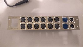
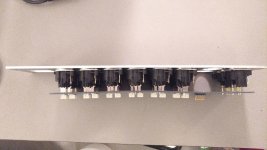
Nat, enlarge those holes or redo the back panel, that tension in the back panel pcb is trouble down the line.
You're probably right !
I intend on making another (I've corrected the CAD) to make two pre-amps so the other will be ok.
I think I'd have to cut the panel in two to remove the extra 2 mm from between those connectors else widening holes will have to be done to all holes to one side of the mistake. I'll make a jig for a multi-tool to keep it straight and bond something to the rear after..
- - - -
I don't need the other 9 PCBs and they might be useful to someone. Therefore I am offering them at 3euro each plus postage (using standard letter post only).
- - - -
Hi all BPPBP preamp builders,
I wonder if stephengrenfell or somebody else has still any leftover PCBs for sale. If so, please contact me by personal message.
Regards
Martti
One more question on parts: the BOM I used lists U3 as TI LM4562MA/NOPB (same as U1, 2, 6, 7) with the remark: "TL072 (as originally proposed) has a DC offset that is way too large and is adding offset of its own."
Is that correct? Is LM4562MA/NOPB the right part to use for U3?
Is that correct? Is LM4562MA/NOPB the right part to use for U3?
I desoldered the oversized caps and put right ones in... This pre-amp does sound really good!
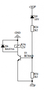
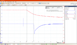
One thing I noticed is quite a loud "pop" at shutdown. I measured at the output and there is a 600 mV negative spike on pin 2 (see attached screenshot). I had not expected that, because I thought relay K3 is there to prevent this kind of thing (see attached detail of the circuit).
Do other people also see/hear this behaviour, or is there something wrong with my build?
Attachments
I desoldered the oversized caps and put right ones in... This pre-amp does sound really good!
One thing I noticed is quite a loud "pop" at shutdown. I measured at the output and there is a 600 mV negative spike on pin 2 (see attached screenshot). I had not expected that, because I thought relay K3 is there to prevent this kind of thing (see attached detail of the circuit).
Do other people also see/hear this behaviour, or is there something wrong with my build?
Plop on both channels or just one channel ?
And why is the red channel, the power supply, only 8 volt, assuming a 10:1 probe.
I doubt whether your reley is working properly given the timescale that you are showing.
Hans
Last edited:
Hi Hans, it is on both channels. The voltage axis of the red channel is displayed on the right of the chart: 16 volt.
I do hear the relay click and checked with a multimeter just now: the resistance between pins 2 and 3 is ~2 ohms at power off, and ~46 ohms at power on. Not sure if these values are as they should be, but it does look like the relay is at least operating. I will try coming weekend to measure the timing of the relay switching, relative to the power down. Any other suggestions are welcome.
I do hear the relay click and checked with a multimeter just now: the resistance between pins 2 and 3 is ~2 ohms at power off, and ~46 ohms at power on. Not sure if these values are as they should be, but it does look like the relay is at least operating. I will try coming weekend to measure the timing of the relay switching, relative to the power down. Any other suggestions are welcome.
Hi Hans, it is on both channels. The voltage axis of the red channel is displayed on the right of the chart: 16 volt.
I do hear the relay click and checked with a multimeter just now: the resistance between pins 2 and 3 is ~2 ohms at power off, and ~46 ohms at power on. Not sure if these values are as they should be, but it does look like the relay is at least operating. I will try coming weekend to measure the timing of the relay switching, relative to the power down. Any other suggestions are welcome.
I see your problem.
Instead of +/- 12Volt you are using+/-16 volt. Nothing wrong with that but the zener should then be 26 volt instead of 18 volt. The transistor is now driven into hard saturation with a base current of ca 6mA instead of 2mA.
Instead of the zener, you could change the 2k2 into 6k8, and you could also lower the lower resistor into 1K.
Hans
- Home
- Source & Line
- Analog Line Level
- BPPBP - Bruno Putzey's Purist Balanced Preamp (well a balanced volume control really)