R5A/B and the opamp U2/7B controls the attenuation and gain.Max gain = 1 for this design?
//
If the vol pot is set to 50% rotation, then the left side of R5 has 5k and the right side of R5 has 5k.
that gives the vol pot gain = 5k/5k = 1times (+0dB).
advance the vol pot all the way to the right to leave 0k to the right and 10k to the left and the gain is 0/10k = silent, or -infinity dB. This would by convention be obtained by turning the vol pot fully anticlockwise.
If your required range of volume adjustment is from silent (~-120dB) to +0dB then you use 50% of the rotation.
http://cms.edn.com/ContentEETimes/Im...ig25_large.jpg
Last edited:
If one needs gain from the R5a/b+U2/7B stage, then one advances the vol pot to the left to use the other 50% of the rotation.
If one turns to 75% rotation one gets 2k5 to the left side and 7k5 to the right side.
The gain is 7k5/2k5 = 3times (+9.54dB)
If you need more gain, then turn the vol pot a bit further.
At 80% rotation the gain becomes 8k/2k = 4times (+12dB)
at 90% rotation the gain becomes 9k/1k = 9times (+19.08dB)
at 95% rotation the gain becomes 9k5/0k5 = 19times (+25.58dB)
at 98% rotation the gain becomes 9k8/0k2 = 49times (+33.80dB)
at 99% rotation the gain becomes 9k9/0k1 = 99times (+39.91dB)
If my memory serves me, you still get about 30dB CMRR with an imbalance of 1K. Obviously using shielded twisted pair for the interconnect is the smart thing to do hear, but I only see benefits from using single ended sources with a balanced reciever. A waste of time its not.
Last edited:
Andrew, I wonder how that would impact the tracking itself between the end-stops. I haven'really looked at it, but someone should do a list of attenuation versus angle with your numbers, in Excel or something and graph the list. Hopefully it will be linear, but I am doubtful.
jan
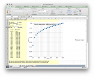
Here are the plots for a Vishay P11S2F0GGSY00D0063, nominally 2x10K conductive plastics pot. I've got this pot in both preamp samples that I have.
I did the measurements because I noticed channel imbalance at high volumes when measuring the preamp performance, and I wanted to know why this happened.
I measured the resistance (Rx) between the CCW end and the taper at 27 approximately equidistant angular positions. Having the exact angle values is not important in this case because I'm comparing the tracking and gain at the same wiper position for both potentiometer elements on the same shaft.
I entered the data obtained into an Excel sheet and analysed the tracking and gain errors for the Bruno's preamp for both the "Pot only" and "Pot + 2K2 resistor" configurations. The front element of the pot is assigned to the left channel, and the rear one to the right channel.
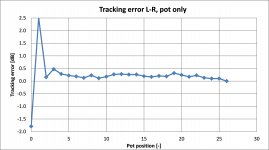
The first plot displays the tracking error between the front (L) and rear (R) pot elements, defined as the quotient between the respective Rx/R ratios, and expressed in dB. Discounting the first two positions, the mean tracking error is approx. 0.25dB for the respective pot element resistances R of 9102 and 9021 Ohms.
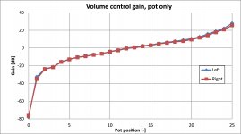
The volume control gain curve that this pot produces in the preamp is shown on the second plot. The useful control range is between approx. -40 and +26dB; as mentioned elsewhere, it becomes "fiddly" at both extreme positions. Observe that the gain law slope increase past position 17, the repercussions of which will be dealt with later. Gain differences between the channels are also clearly visible in this region.
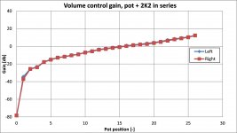
Using the data measured to calculate the gain control law if a 2K2 resistor were connected in series with the pot, I obtained the volume control gain curves of the third Figure. The gain law between positions 5 and 26 has an almost perfect "linear in dB" characteritics, and the gain differences at high pot settings are not pronounced. Note that the addition of the 2K2 resistor limits the volume control stage gain to about 12dB.
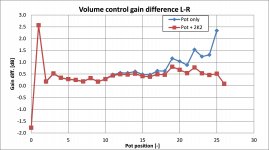
Plotting now the gain differences between the channels for both configurations (the fourth Figure), it can be seen that the gain difference in the configuration "Pot only" increases as the stage gain is increased, reaching values that become audible from the pot position 19 (resistance approx. 6.5K out of 9K total for this pot) onwards. The configuration "Pot + 2K2" does not change its channel imbalance as much in this region, staying roughly around 0.5dB on the average. The reason for the latter behaviour is that the additional resistance diminishes the gain sensitivity with regard to the pot imperfections at high CW pot settings. This can be proved mathematically by taking the gain derivative with respect to the resistance ratio; I did it, but I omit the proof here in order not to overload the post.
On the basis of these results, I can conclude that the addition of a series resistance of 2K2 to this particular pot has improved the channel imbalance at high volumes; the price to pay is the reduction of the maximum volume control stage gain. In my case, it was the effect I sought anyway.
Regards,
Braca
Attachments
Thanks Dni, that confirms my experiments with an active inverting opamp gain/attenuation control.
Adding in the limiting gain resistor at one end significantly reduces the balance error where the curve steepens. That's the series 2k2 you used.
Reducing maximum gain to 0dB:
I also looked at swapping out the 10k VR and replacing it with a 5k VR then adding in 5k1 of series resistor. This gives a maximum gain of ~0dB, i.e. virtually a no gain Buffer.
The total resistance before the -IN becomes ~10k and does not introduce significant noise. The standard arrangement uses the 10k vol pot as the total resistance before the -IN and it too equals 10k.
I also looked at adding in a resistor inside the out to -IN feedback loop.
This too has the effect of reducing the balance error as well as reducing the maximum attenuation.
The clue to balance errors are the very steep parts of the curve as one moves from the "constant slope" in the middle 80% of rotation.
It's the "steepness" at the end of travel that gives rise to the balance errors.
Reducing this slope to nearer the constant slope makes for a low error balance and gives a nice controlalble gain through the whole rotation range of the vol pot, that is more tolerant of small track to tracks resistance differences.
These two added resistors need to "match" the actual resistance of the vol pot track. They can be trimmed to get an exact channel balance when the contol is at either extreme rotation. It may be better to trim the added resistors when the rotation is just off the end stops and both wipers are on the resistive track.
I attach the spreadsheet that shows the effect of these two added resistors (4 in a two channel vol pot).
remove the .txt to leave a .ods open spreadsheet.
I think excell will open an .ods file.
If not, I can export an excel style and attach that as well.
The .ods file is not opening.
I will do an excel .xls version. The .txt has to be renamed to .xls
It is not opening either.
Attachments
Last edited:
Here are the plots for a Vishay
Braca
Braca, I understand these plots are from measuring the various pot parts versus position.
What I would like to see is the percentage or ratio of Rx/R for each position for each individual pot. While the pot may have different total values end-to-end, do the ratios track with position?
Maybe I didn't read your post correctly, but I think what you show is something different, rather values of Rx and R between pots. For this volume control, what is determining is the Rx/R ratio tracking versus angle between pots.
In other words, if one pot is 10k, the other is 11k, but in the 50% position one is 5k/5k and the other 5.5k/5.5k, that would still be perfect tracking in this context.
Jan
How does one attach a spreadsheet?
I have attached spreadsheets with Open Office and it worked.
Today I have Libre Office and it does not work.
Is Libre Office the problem?
Andrew it might be that the Libre office file extension is not known/accepted by the forum.
I tried exporting in xls
that part is OK.
I can change the .xls to .txt
that allows me to attach. OK so far.
But when I click on the attachment it saves it as a .TXT, so I need to rename back to .xls.
This is where it goes wrong.
Libre Office cannot read the renamed download.
Instead it asks via a complicated dialogue box to confirm lots of settings. Clicking OK on the pre-filled out dialogue box gives rubbish.
Can anyone read either the .xls, or .ods, spreadsheets using their software?
Last edited:
Jan, you see that right.Braca, I understand these plots are from measuring the various pot parts versus position.
What I would like to see is the percentage or ratio of Rx/R for each position for each individual pot. While the pot may have different total values end-to-end, do the ratios track with position?
Maybe I didn't read your post correctly, but I think what you show is something different, rather values of Rx and R between pots. For this volume control, what is determining is the Rx/R ratio tracking versus angle between pots.
In other words, if one pot is 10k, the other is 11k, but in the 50% position one is 5k/5k and the other 5.5k/5.5k, that would still be perfect tracking in this context.
Jan
If the RATIO 5k:5K is exactly the same as the RATIO 5k5:5k5, then there is no balance error. But the different track resistances require trimming of the added resistors.
I think the comparison needs to look at dB of attenuation, or dB of gain and compare the difference between channels to see if the balance error changes with rotation. If it is always 0.2dB higher on one channel, then the balance is not changing.
If at some part of the track it changes from -0.2dB elsewhere to -0.65dB, then the balance error is -0.65dB -(-0.2dB) = -0.45dB at that setting
It appears to me that the overlay of blue and red shows how the balance changes with pot rotation.
Last edited:
I tried exporting in xls
that part is OK.
I can change the .xls to .txt
that allows me to attach. OK so far.
But when I click on the attachment it saves it as a .TXT, so I need to rename back to .xls.
This is where it goes wrong.
Libre Office cannot read the renamed download.
Instead it asks via a complicated idalogue box ro confirm lots of setting. Clicking OK on the pre-filled out dialogue box gives rubbish.
Can anyone read either the .xls, or .ods, spreadsheets using their software?
I have no problem. Just don't open it after download, you'll get gibberisch. Save it, and take off the .txt part making it an .ods file. That can then be opened as usual with Open Office.
Jan
Jan, you see that right.
If the RATIO 5k:5K is exactly the same as the RATIO 5k5:5k5, then there is no balance error. But the different track resistances require trimming of the added resistors.
But wasn't the whole idea NOT to use added resistors to maintain the good tracking with angle?
Jan
That's where B.Putzeys' use of "linear" in his explanation does not make sense to me. And why I came here to try to get to the bottom of what has been offered and how I think it can be improved.But wasn't the whole idea NOT to use added resistors to maintain the good tracking with angle?
Jan
The RANGE of adjustment of the standard circuit is enormous. At least 110dB and only the middle 80%, or so, is usable because the balance and the gain go out the window in the top 10% and bottom 10% of the rotation.
Adding limiting resistors improves the "linearity". But B.Putzeys never mentions that.
When I first read his article I thought he was talking about amplification (as in distortion) linearity. But this Thread has since confirmed he was only talking about the linearity of the control law of the vol pot.
When one looks at Dni's curve, for no added resistor, you see the steepening at both the bottom and the top of the curve. It's this steepening (Dni refers to differentiating the curve and that equates to analysing the "SLOPE") that tells one that the circuit has become very intolerant of small imbalances of track resistance.
Adding limiting resistors improves the circuits TOLERANCE to small resistance imbalances by reducing the steepness of the curves. The disadvantage is that the added resistors reduce the range that is available. It's the REQUIRED range of adjustment that finally determines what value of added resistors are of use to each Builder.
If you have my .xls open you can set the 47r and 5k1 to minimum values and see the steepness of the standard circuit curve at the extremes of the vol pot rotation.
Last edited:
I am happy to see that some are able to open that spreadsheet.I can also open the .txt just fine after renaming it to .xls.
It's odd that my Libre Ofiice cannot open it's own export after adding and removing the .txt to the file name.
post275.
You can set the three values in the white boxes to any values to see the effect on the control law.
Rs and Rf can go down to ~0.5
Vol pot can go back to 10 (k is already in the formulae)
That will show a very similar curve to Dni's.
Then step the values of Rs and Rf upwards to see the constant slope part extending to a wider range of rotation.
I can get from 5% to 100% using the values in the download. that gives a range of adjustment from -30dB to -0.1dB. That range suits most of my listening if I have a lowish gain amplifier.
IIf I use a higher gain amplifier I need more range of attenuation -40dB to -10dB might suit, but since I have not built B.Putzeys balanced vol pot, I would need to set up some different experiment.
Each Builder can select the added resistors to suit THEIR required range of adjustment.
An alternative very wide range attenuator could set Rs to 1r0 and Rf to 10r. That gives a range of 140dB (-80dB to +60dB) and the middle 90% is usable.
BTW,
the two pages are both "protected" but without a password.
When protected only the three white cells are selectable/changable.
All the yellow cells cannot be overwritten.
If you go to tools - protect - sheet you can unprotect that sheet, if you need to make changes (like language to something that makes better sense, or change a formula) Then tools - protect - sheet and save and that preserves all the formulae.
Saving without a password works in Excel, Open Office and in Libre Office.
Last edited:
Braca, I understand these plots are from measuring the various pot parts versus position.
What I would like to see is the percentage or ratio of Rx/R for each position for each individual pot. While the pot may have different total values end-to-end, do the ratios track with position?
Maybe I didn't read your post correctly, but I think what you show is something different, rather values of Rx and R between pots. For this volume control, what is determining is the Rx/R ratio tracking versus angle between pots.
In other words, if one pot is 10k, the other is 11k, but in the 50% position one is 5k/5k and the other 5.5k/5.5k, that would still be perfect tracking in this context.
Jan
Jan, initially I thought in the same way as you, but the prospect of having to build a mechanical jig for this measurement got me thinking as to whether the rotation angle is needed at all, at least for establishing the volume control tracking error. The conclusion was that it was not needed, and here is the logic behind it.
My interest was to find out how well the two pot elements track in terms of their respective Rx/R values along the path from 0 to 300 Deg. of mechanical travel specified for this pot. The angle coordinate determines the horizontal positions of the individual Rx/R ratios on the chart, but at each angle value on the abscissa one must find the respective pot elements' Rx/R values measured at the same shaft position in accordance with the sequence "set pot position->measure RxLeft->measureRxRight->repeat".
In this way I'm able to compare the pot tracking at a number of discrete positions that are not strictly equidistant in terms of the rotation angle, but the only effect the angle would have had is to shift each of the points measured by a few Deg. to the left or right. So the gain law curve would possibly look a bit different, but this in no way invalidates the tracking values obtained; and the gain law is of less importance in comparison with the channel imbalance.
For example, at point #4 (approx. 9 o'clock) I have (Rx/R)Left=0.145, GainLeft=-15.4dB, (Rx/R)Right=0.141, GainRight=-15.7dB, Gain tracking error = GainLeft-GainRight=0.3dB (see Figure #4 in the post)
Given that the individual linearity tolerance of this pot model is +-5% (+-0.43dB), tracking errors up to the latter value are unavoidable, which is clearly visible in the Figure.
I hope this helps clarifying the results presented.
Regards,
Braca
Last edited:
Do they give us track linearity tolerance for linear vol pot?
The standard tolerance given for vol pots is the track resistance tolerance.
A 10k 5% tolerance vol pot can measure end to end at 9k5 to 10k5 That's our 5% tolerance.
I cannot recall seeing the smallest "on track" resistance before the wiper lifts off the track and enters the near zero ohms region of the metal/metalised end termination.
Last edited:
- Home
- Source & Line
- Analog Line Level
- BPPBP - Bruno Putzey's Purist Balanced Preamp (well a balanced volume control really)