did you find the sets of articles linked in the Threads?
if you DAC is unbalanced why are you proposing using a Bal to unbal conversion feeding into a vol pot?
Just feed the unbal output into a vol pot and then feed vol pot output to the receiver.
You mean that I can skip all of the Bruno preamp's buffer stage?
Damian
Please confirm that 9Vac drives the Receiver to maximum output voltage.
I would adopt a pre-amp gain stage with a bit more output capability.
Maybe ±20Vdc to ±24VDC supply rails and discrete output devices that can source a bit more current. This should get you to +22dBu (9.75Vac) to maybe +24dBu (12.28Vac)
What does that mean?difficult load of UCD amplifier core.
I would adopt a pre-amp gain stage with a bit more output capability.
Maybe ±20Vdc to ±24VDC supply rails and discrete output devices that can source a bit more current. This should get you to +22dBu (9.75Vac) to maybe +24dBu (12.28Vac)
Last edited:
It does up to +18dBm out, which is a bit less than you need but in spitting distance.
So +18 dBm means maximum 63 mW of power is delivered into output? And what about maksimum output voltage level? I'm sorry for all that question but it seems this excellent preamplifier lacks of information necessary for many DIY-ers.
See this document:
http://hifisonix.com/wordpress/wp-content/uploads/2010/10/X-Altra-Mini-V2.0.pdf
There on page 14 is clearly stated " distortion vs Output signal level into 600Ohms. At 9Vrms out (...)" and I clearly know what are the capabilities of that preamp. Here in Bruno preamp this is not as easy to understand what it is capable of.
Sorry 18dBU. Tool long working with RF comms and I type dBm without thinking.
I think you misunderstand what this preamp is about. I know people want the moon on a stick for nothing, but this was a proof of concept for a way of doing balanced vol control. Shouldn't be much work to calculate the input impedance as its a std instrumentation amp front end.
But as Andrew says, its at least 3dB cold for you IF you want to drive your power amp to clipping.
Please confirm that 9Vac drives the Receiver to maximum output voltage.
What does that mean?
I would adopt a pre-amp gain stage with a bit more output capability.
Maybe ±20Vdc to ±24VDC supply rails and discrete output devices that can source a bit more current. This should get you to +22dBu (9.75Vac) to maybe +24dBu (12.28Vac)
Andrew, what is a receiver in your nomenclature? Is this referred to the preamplifier or my UCD400? Yes, UCD400 without its own buffer requires 8,9 Vrms to get to maksimum output. Its buffer uses TL072 and sound quality is immediately drowned after switching to buffered input. I use it unbuffered and driven from 2V rms NE5532 DAC output stage so it have not even close to 400W. 6-7Vrms will be sufficient as I don't need so much RMS power.
Last edited:
ubal output from DAC to unbal input to vol pot.
unbal output from vol pot to unbal input of preamp.
+12dB, or +15dB gain pre-amp
unbal output pre-amp to unbal input of Receiver.
If the Receiver has a Bal input, then adopt the bal output shown in B.Putzeys sch.
It is just a few extra passive components and an XLR socket.
The Receiver is the next stage that receives the signal.
Last edited:
8.9Vac is equivalent to 12.6Vpk, or 25.2Vpp
You would need supply rails exceeding that peak to peak by at least 2V. But most low level stages are not designed for rail to rail output (that is special design adopted in some IC and brings with it other compromises to performance). That is probably why the tl072 performs badly as a gain stage.
That is why I suggested ±20Vdc as supply rails to get the output well away from clipping and well below the level where distortion begins to increase markedly.
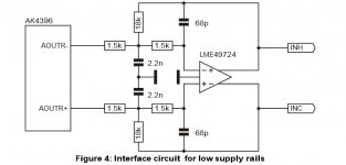
No I don't want to fly to the Moon on this preamp. ") I found this preamp as candidate to the simple and quality interface between single-ended DAC output and differential inputs of the UCD amplifier. I like idea no using any potmeters straight in signal path. Another candidate is LM49724 circuit from NC500 datasheet you see in attachment.
I found this preamp as candidate to the simple and quality interface between single-ended DAC output and differential inputs of the UCD amplifier. I like idea no using any potmeters straight in signal path. Another candidate is LM49724 circuit from NC500 datasheet you see in attachment.
Is there a problem in connecting single ended source to differential output of this preamp? If I remember correctly Hypex guys frequently are saying there is nothing wrong with it. Regarding this preamp: It will be sufficient if it will drive an output to the 18 dBu level (6,1 Vrms) and will have +14dB of voltage gain in the same time without strain but I need to proove it before I pull the trigger and pay my money. Your answers will help to another DIYiers also so thank you for your answers
I found this preamp as candidate to the simple and quality interface between single-ended DAC output and differential inputs of the UCD amplifier. I like idea no using any potmeters straight in signal path. Another candidate is LM49724 circuit from NC500 datasheet you see in attachment.Is there a problem in connecting single ended source to differential output of this preamp? If I remember correctly Hypex guys frequently are saying there is nothing wrong with it. Regarding this preamp: It will be sufficient if it will drive an output to the 18 dBu level (6,1 Vrms) and will have +14dB of voltage gain in the same time without strain but I need to proove it before I pull the trigger and pay my money. Your answers will help to another DIYiers also so thank you for your answers
Attachments
Ok so let me summarize things:
1. This preamp accepts input voltage level up to 18 dBu and outputs up to 18 dBu signal level before it starts clipping. This is on +/-12V supply voltage. Input / output maximum signal voltage is 17.4V p-p.
2. Preamp can attenuate its output from 0 dB to -xx dB but input signal level is limiting factor for output level.
3. Preamp can apply gain from 0dB to +xx dB but then output signal level is limiting factor.
4. Noise floor of this preamp is so low that voltage gain can be set relatively high, for example +20dB voltage gain (10x). In this case input signal voltage cannot be higher than 0,6 V rms becouse higher level will clip at the output.
5. One can change preamp power supply voltage from +/-12V do +/-15V for higher input / output signal level without clipping.
6 Preamp can accept single-ended input from resistor ladder DAC. Negative input is shorted to the ground. Signal can be fed by XLR cable
7. Someone has advised me to change gain of buffer stage of this opamp from 1x to 4x for some reason. What is the reason for this?
Please correct me if I understand this preamp wrong or if my assumptions in points listed above are wrong. I want to understand this concept well before make.
Last edited:
Convert your DAC to balanced impedance output.
ONLY AFTER you have done that, can balanced impedance pre-amp offer you any interference rejection improvement.
If you don't convert and keep the DAC as unbalanced output, then use an unbalanced pre-amp with conventional vol pot followed by the unbalanced gain stage.
Is your Receiver balanced impedance input, or unbalance input?
Have a look at Jensen's ap note 003.
It's here on the Forum and lots of references to section 2.4.
I mistakenly called it pseudo balanced in my early references.
Last edited:
most digital and CDP have a 0dbfs signal of around 2Vac (6Vpp, 3Vpk)change gain of buffer stage of this opamp from 1x to 4x for some reason. What is the reason for this?
If your sensitivity for max power is 8.9Vac or 9Vac then you need gain.
9V/2V = +13.1dB
you definitely don't need +20dB for a 2Vac 0dBfs.
but some digital equipment has a much lower output.
Do you have any with <<2Vac?
If so then you could use a switchable gain block and only turn on the higher gain when you need it. Distortion and noise go up when you increase the gain.
And if you are in a lower level listening mood, then you don't turn up the gain at all, even for very low level Sources.
I have suggested switchable pre-amp with +0dB, +6dB and +12dB for universal use when some extra gain is required for loud listening sessions, but retain the big advantages of the +0dB Buffer stage for all other listening.
Last edited:
Convert you DAC to balanced impedance output.
ONLY AFTER you have domn that, can balanced impedance pre-amp offer you any interference rejection improvement.
If you don't convert and keep the DAC as unbalanced output, then use an unbalanced pre-amp with conventional vol pot followed by the unbalanced gain stage.
Is your Receiver balanced impedance input, or unbalance input?
Have a look at jensens ap note 003.
It's here on the Forum and lots of references to fig
Receiver has differential input. It is designed by Bruno so I think it has balanced impedance input.
Soekris DAC has onboard buffer with unbal to bal converter wchich can supply 4Vrms differential signal. I wanted to bypass it to get to raw output from resistor ladder directly which is 1.4 Vrms single ended.
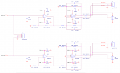
This DAC bal-unbal converter and buffer scheme is linked below.
Attachments
Is it balanced impedance input?
Differential means something quite different !
Differential applies to most common opamps that have +IN and -IN pins and to most Power Amplifiers.
That's the whole purpose of a two wire input.
The amplifier reads the voltage difference across the two wires and scales that voltage difference to reproduce as near an exact copy of that audio signal. Then sends that audio signal down two wires as a differential signal.
If you disable the balanced impedance output and use the unbalanced output, then you don't need a balanced input pre-amp.
9V/1.4V is a gain difference of 19.1dB
Have you looked at the 49724 datasheet?
On ±15Vdc it has a guaranteed (limit) maximum output of 50Vpp into 600ohms.
On a 36V supply it would be slightly higher.
That output stage suits the input of your Power Amp.
All you need is to contact the manufacturer and ask them to supply the two gain setting resistors to drive your Power Amplifier to maximum output.
That is what you should have asked in your first post. Instead of hiding all the information you had to hand !!!!!!!
OH !
and check that Pin1 is connected to Chassis and NOT to Power Ground.
Last edited:
Is it balanced impedance input?
Differential means something quite different !
Differential applies to most common opamps that have +IN and -IN pins and to most Power Amplifiers.
That's the whole purpose of a two wire input.
The amplifier reads the voltage difference across the two wires and scales that voltage difference to reproduce as near an exact copy of that audio signal. Then sends that audio signal down two wires as a differential signal.
Andrew I cannot understand it all, you could take a quick look into this document:
http://www.hypex.nl/docs/appnotes/gain_appnote.pdf
Where on the first page basic input circuit topology of Receiver is explained.
Damian
Last edited:
where did you get that from?single-ended 1.4V rms output / 625 Ohms output impedance.
If you can't read a schematic then ask the manufacturer how to interface the two components.
My post217 explains in more detail.
Hypex shows how to change the gain.
This information is here:
https://hifiduino.wordpress.com/2015/01/30/building-soekris-r-2r-dac/
The manufacturers often do not want to bother with unusual causes, especially when someone is not so much knowledgeable as me.
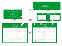
Someone should explain me patienly point-to point method what would be best and simplest way to connect DAC and amplifier with circuits available below. I have even made block diagram of my desired system... I will post it here but every further discussion regarding this issue should be directed to my PM in order to avoid rubbish in this thread. Thanks! I will read through all your answers throughly later in the day when I come back home.
https://hifiduino.wordpress.com/2015/01/30/building-soekris-r-2r-dac/
The manufacturers often do not want to bother with unusual causes, especially when someone is not so much knowledgeable as me.
Someone should explain me patienly point-to point method what would be best and simplest way to connect DAC and amplifier with circuits available below. I have even made block diagram of my desired system...
I will post it here but every further discussion regarding this issue should be directed to my PM in order to avoid rubbish in this thread. Thanks! I will read through all your answers throughly later in the day when I come back home.Attachments
Last edited:
- Home
- Source & Line
- Analog Line Level
- BPPBP - Bruno Putzey's Purist Balanced Preamp (well a balanced volume control really)