As I said, I feel subjective listening enough balanced in the medium volume range in I use, positions 15 to 30.
But it bothers me some things:
1- each time I perform ''Adjust Bias'' I need to adjust again at some degree, I remember one time even out of the range 500/1000ohm,
2- no matter if I edit and upload the measured LDR values, always I tested same results found at min. vol. shunt / max. vol. series.
3- also I edited on firmware, down to half both Nom. impedance and Load impedance (exactly 6k/47k) but same no effect, always found same results shown on previous post.
Just I performed right now a new bias adjustement /new calibration cicle, and no success. Error 1, left series could not be calibrated.
Freeze
Hey there, i am very happy with Nebs AIO board,
but after a year of normal operation it started showing error 20 after startup.
i tried re-calibrating but discovered that my LDRs have increased resistance up to 239r.
i replaced them with 4 NSL-32SR2 and now the controller starts without error, but i cannot change volume, change channels etc.
it seem frozen!
i checked soldering, reloaded the firmware, but with no effect. still frozen.
i measured the 5v, and it dropped from 4.96V to 4.19V.
is there any other part i need to change if switching from SR3 to SR2?
i hope someone has an idea,
i doesn't seem to be the encoder since remote doesn't work either..
Hello,
- I/O switching is done with best quality latching relays with Silver-Palladium contacts, to avoid any degradation of the musical signal
Hi,
quick question
I see that you're using Panasonic AGQ20012 - the non-latching relay part, and on the circuit board the connection for a selection is via 3+4 and 5+6. Thus the relay coils need to be operating to select the line. The non-selected lines are sat with no voltage.
Naturally this means on startup no inputs are connected.
Do you know if the relay simply carries the signal over the metal bar that contacts the metal core inside the relay coil?
During operation the selected line has a powered coil hot and possibly a contacting metal core near the signal path. What additional noise does this cause?
Also given that the coil in the relay doesn't need full current to maintain the contact - does the system back off the power to coil following selection?
Lastly - is there a flyback diode across the relay coils?
Last edited:
@JOIMONF, mine is a pain in the a** to calibrate too.
It seems really temperature dependant and if I need to recalibrate it I must plan some hour to avoid error 1.
When calibration is done it works well though
Thanks t-minik, at your suggestion I performed repetitive calibration cicles, and I have succeed, so very grateful to you.
I calibrated after 5 /6 cicles fail.
I repeated twice and same, success after same aprox. 5 or 6 fail.
Looks like you have a problem with something on i2c bus that can easily mess up arduino. This bus connects display, arduino and mcp23008, so start from there. Disconnect display first and listen if arduino boots - relays should click.
Thank you Neb!
it was enough to point me in the right direction. i checked the display fist but i found out that i somehow blew the nano during my changes on the board.
with a new nano it is working again!
i was also wondering if anyone has used big letters instead of the channel numbers in the display? BT, TV etc.
i think it doesn't work with the selected font.
my Arduino skill's are pretty limited, i know.
Thanks already!
Jürgen
Hi there! I lost the PCBs I got from Chris... So, anyone is sparing a kit for 2 ins / 2or3 outs ?
Ok, I know it's quite necroposting, but I found the original PCBs...
PSU v1.8+mainboard+outs.
I'm not going to use them, family is getting bigger so time is fewer.
If anyone interested, PM me.
Hi
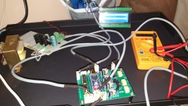
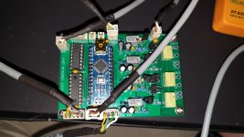
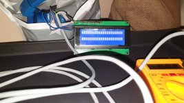
after a long time finished ldr controller but I have a problem. Nothing appears on the screen. I used vn2222ll-g instead of 5ln01sp except that all parts are the same.
what could be the problem. I checked the links many times. When I measured the ldr outputs, I could only set 1. ldr 700k, others do not read the value.
Attachments
Ok thats normally an issue with either A+ or R+ supply rails according to the troubleshooting portion of the manual. You can find the manual in the zip archive in post 1 of this thread. Can you double check this please?
Also I think you have one of the original boards rather than the AIO boards from zdr?
If so please comment out (use // at the start of the line) line 105 like this :
//#define AIO //** enables AIO (All-In-One) PCB, comment out for original PCB
Also comment out line 30 (unless you want a home theatre (HT) bypass input). viz :
// Home theatre input
//#define INPUT_FOR_HT
Note also the firmware version I posted has impedance selection capability on start up.
So you should power on first time holding the encoder button down to set it. Keep holding it down and rotate to select desired impedance then release. I suggest you set it to 10K to begin with.
Last edited:
wineds i am using firmware from you
I corrected the codes as you wish and set the impedance to 10k.
I changed the input and output configurations. I'm testing it as 1 input and 1 output for now.
After doing the calibrations, I will have to correct the codes line 1349 to 1355 for remote control.
I corrected the codes as you wish and set the impedance to 10k.
I changed the input and output configurations. I'm testing it as 1 input and 1 output for now.
After doing the calibrations, I will have to correct the codes line 1349 to 1355 for remote control.
- Home
- Source & Line
- Analog Line Level
- Arduino based LDR volume and source selection controller