Something strange is going on with my 8V feed to Nano...
Problem solved. I had the IC2 installed wrong way. Now the voltages are as they should. Now I'll just have to wait for the display to arrive so I can continue this little project.
My custom code for OLED and LCD displays is here:
https://drive.google.com/drive/folders/0B74euvw8ey5JOENmRXNYUEtySVE
It should work out of the box with All-In-One pcb.
If you are using external PCB, you need to swap R5 and R6 in the code. Tested with 5 inputs and 2 outputs only, likely to have bugs in other IO combinations.
https://drive.google.com/drive/folders/0B74euvw8ey5JOENmRXNYUEtySVE
It should work out of the box with All-In-One pcb.
If you are using external PCB, you need to swap R5 and R6 in the code. Tested with 5 inputs and 2 outputs only, likely to have bugs in other IO combinations.
My custom code for OLED and LCD displays is here:
https://drive.google.com/drive/folders/0B74euvw8ey5JOENmRXNYUEtySVE
It should work out of the box with All-In-One pcb.
If you are using external PCB, you need to swap R5 and R6 in the code. Tested with 5 inputs and 2 outputs only, likely to have bugs in other IO combinations.
Thank you VERY Much, zdr.
Isn't it works for original PCB??
The code I posted is basically the same as original from OP, with these differences:
1) bugfixes for remote repeat and 0 volume power-on burst from Chris
2) you can choose between 1602 and 2004 displays, also coded by Chris
3) eliminated muting during fast channel switching with left/right buttons (can be easily turned back on, by uncommenting one line of code)
4) menu button direct output switching, for two outputs only
5) Relays 5 and 6 switched places in code. Original code uses Relay 5 to switch outputs, I am using relay 6 for this purpose. Delay relay is not used.
I can also post code without change 5) which should work with controller PCBs attached to original external (balanced) IO PCB variants, but it's easier to simply swap relay 5 and 6 wires.
"My" all-in-one (AIO) PCB is the same as original, with main difference being single-ended 5X2 IO PCB attached to it, to eliminate the wires between controller and IO. You can still use it as original controller PCB with external IO boards, by simply cutting off (or ignoring) attached IO part. AIO PCB uses non-latching relays which are constantly powered on through darlington array. I could not hear any interference whatsoever from DC powering the relays, but it might make some people nervous, so they would need to opt for separate IO PCB with latching relays (and mess with more wires and longer signal path in the process")
To make OLED variant as fast as LCD, I had to resort to SSD1306 ASCII library, which does not contain any graphical commands. All the graphics is printed as font, so some custom fonts needed to be integrated. They are included in the OLED folder. OLED variant is still bigger and cannot be debugged due to mem isssues, unless you turn off some parts of the code (like calibration for example). I maximised space used on the OLED, so that even smallest 0.96" OLEDs are visible from moderate distance. OLED has to be 128X64 SSD1306 based with I2C interface for the code to work. OLED does not have backlight, so it releases backlight pin to be reused for something else in case you need it.
All the modifications I made are extremely minor, and full credit is to be redirected to original designer and OP. Same goes for complaints
I am currently playing with ESP8266, so this project might soon become IoT aware
1) bugfixes for remote repeat and 0 volume power-on burst from Chris
2) you can choose between 1602 and 2004 displays, also coded by Chris
3) eliminated muting during fast channel switching with left/right buttons (can be easily turned back on, by uncommenting one line of code)
4) menu button direct output switching, for two outputs only
5) Relays 5 and 6 switched places in code. Original code uses Relay 5 to switch outputs, I am using relay 6 for this purpose. Delay relay is not used.
I can also post code without change 5) which should work with controller PCBs attached to original external (balanced) IO PCB variants, but it's easier to simply swap relay 5 and 6 wires.
"My" all-in-one (AIO) PCB is the same as original, with main difference being single-ended 5X2 IO PCB attached to it, to eliminate the wires between controller and IO. You can still use it as original controller PCB with external IO boards, by simply cutting off (or ignoring) attached IO part. AIO PCB uses non-latching relays which are constantly powered on through darlington array. I could not hear any interference whatsoever from DC powering the relays, but it might make some people nervous, so they would need to opt for separate IO PCB with latching relays (and mess with more wires and longer signal path in the process
To make OLED variant as fast as LCD, I had to resort to SSD1306 ASCII library, which does not contain any graphical commands. All the graphics is printed as font, so some custom fonts needed to be integrated. They are included in the OLED folder. OLED variant is still bigger and cannot be debugged due to mem isssues, unless you turn off some parts of the code (like calibration for example). I maximised space used on the OLED, so that even smallest 0.96" OLEDs are visible from moderate distance. OLED has to be 128X64 SSD1306 based with I2C interface for the code to work. OLED does not have backlight, so it releases backlight pin to be reused for something else in case you need it.
All the modifications I made are extremely minor, and full credit is to be redirected to original designer and OP. Same goes for complaints
I am currently playing with ESP8266, so this project might soon become IoT aware
My custom code for OLED and LCD displays is here:
https://drive.google.com/drive/folders/0B74euvw8ey5JOENmRXNYUEtySVE
It should work out of the box with All-In-One pcb.
If you are using external PCB, you need to swap R5 and R6 in the code. Tested with 5 inputs and 2 outputs only, likely to have bugs in other IO combinations.
Since zdr/Neb was so kind to share his code, I thought and asked his permission to upload it on GitHub, so it's more a "robust" sharing and it frees him to have it stored on his GDrive.
It's here: https://github.com/ghiglie/diyaudio-ldrcontroller/tree/develop
{ branch development }
I applied a GNU GPLv3. All credits are to respective actors in this thread.
I'm not the maintainer of code or similar, since my board is still in WIP, but I hope this helps. I'll try to get a good ReadMe for it.
Thank You zdr and all others who have made this project available. I managed to get it running by using zdr's AIO board and 1602 LCD display. Haven't tried it with actual music signal yet, but everything seems to be in order after successful calibration and some DMM measurements.
I had to install some special USB drivers for my Arduino Nano, as it is probably some kind of clone version. Also the LCDADDRESS parameter had to be changed to 0x27 with my display. After these trials and errors everything worked ok.
I had to install some special USB drivers for my Arduino Nano, as it is probably some kind of clone version. Also the LCDADDRESS parameter had to be changed to 0x27 with my display. After these trials and errors everything worked ok.
Since zdr/Neb was so kind to share his code, I thought and asked his permission to upload it on GitHub, so it's more a "robust" sharing and it frees him to have it stored on his GDrive.
It's here: https://github.com/ghiglie/diyaudio-ldrcontroller/tree/develop
{ branch development }
I applied a GNU GPLv3. All credits are to respective actors in this thread.
I'm not the maintainer of code or similar, since my board is still in WIP, but I hope this helps. I'll try to get a good ReadMe for it.
Thanks for doing this. It would be a shame to lose the code.
Thanks for doing this. It would be a shame to lose the code.
I did not that much!
I was mainly concerned about losing the code too, and after that, have a "notepad" to track interesting modifications.My custom code for OLED and LCD displays is here:
https://drive.google.com/drive/folders/0B74euvw8ey5JOENmRXNYUEtySVE
It should work out of the box with All-In-One pcb.
If you are using external PCB, you need to swap R5 and R6 in the code. Tested with 5 inputs and 2 outputs only, likely to have bugs in other IO combinations.
Hi Zdr,
To swap R5 and R6 in the code, should I change the code like below??
#define PIN_EXT_R1 1 // port extender: relay 1
#define PIN_EXT_R2 2 // port extender: relay 2
#define PIN_EXT_R3 3 // port extender: relay 3
#define PIN_EXT_R4 6 // port extender: relay 4
#define PIN_EXT_R5 5 // port extender: relay 5
#define PIN_EXT_R6 4 // port extender: relay 6. Used for delay relay
#define PIN_EXT_BIAS 7 // port extender: BIAS
-----> #define PIN_EXT_R5 4
-----> #define PIN_EXT_R6 5
IR Remote...
Hi zdr,
I succeed 1602 LCD with your code.
but Apple silver remote controller didn't work.
[this is the code what not work with silver apple remocon]
int getIRkey() {
c1 = c2 = c3 = c4 = 0;
duration = 1;
bool repeat = false;
while ((duration = newpulseIn(PIN_REMOTE, HIGH, 15000)) < 2000 && duration != 0)
{
// Wait for start pulse
}
//PRINTLN(duration);
if (duration == 0) // This is an error no start or end of pulse
return (255); // Use 255 as Error
if (duration < 3000) { // This is the repeat
//PRINT("repeat\n");
repeat = true;
}
if (duration < 5000) { // This is the command get the 4 byte
mask = 1;
for (int i = 0; i < 8; i++) { // get 8 bits
if (newpulseIn(PIN_REMOTE, HIGH, 3000) > 1000) // If "1" pulse
c1 |= mask; // Put the "1" in position
mask <<= 1; // shift mask to next bit
}
mask = 1;
for (int i = 0; i < 8; i++) { // get 8 bits
if (newpulseIn(PIN_REMOTE, HIGH, 3000) > 1000) // If "1" pulse
c2 |= mask; // Put the "1" in position
mask <<= 1; // shift mask to next bit
}
mask = 1;
for (int i = 0; i < 8; i++) { // get 8 bits
if (newpulseIn(PIN_REMOTE, HIGH, 3000) > 1000) // If "1" pulse
c3 |= mask; // Put the "1" in position
mask <<= 1; // shift mask to next bit
}
mask = 1;
for (int i = 0; i < 8; i++) { // get 8 bits
if (newpulseIn(PIN_REMOTE, HIGH, 3000) > 1000) // If "1" pulse
c4 |= mask; // Put the "1" in position
mask <<= 1; // shift mask to next bit
}
c3 >>= 1; // Discard the least significant bit
//PRINTLN(c1); PRINTLN(c2); PRINTLN(c3); PRINTLN(c4);
if ((c1 == 238) && (c2 == 135) /*&& c4 == 131*/) { // Only return valid Apple remote codes
// if ((c1 == 0) && (c2 == 255) /*&& c4 == 131*/) { // Only return dodgy Asda subwoofer remote codes
//PRINTLN(c4);
return (c3);
}
if (repeat && (c3 == 2) or repeat && (c3 == 4)) // Only way to verify a repeat from this remote is with the 2 code?
return (0);
}
return (255);
}
#pragma endregion
When I changed the code for IR reomote part with original code, it's work.
[this is the original code what work with silver apple remocon]
int getIRkey() {
c1 = c2 = c3 = 0;
duration = 1;
while ((duration = pulseIn(PIN_REMOTE, HIGH, 15000)) < 2000 && duration != 0)
{
// Wait for start pulse
}
if (duration == 0) // This is an error no start or end of pulse
return (255); // Use 255 as Error
else if (duration < 3000) // This is the repeat
return (0); // Use zero as the repeat code
else if (duration < 5000) { // This is the command get the 4 byte
mask = 1;
for (int i = 0; i < 8; i++) { // get 8 bits
if (pulseIn(PIN_REMOTE, HIGH, 3000) > 1000) // If "1" pulse
c1 |= mask; // Put the "1" in position
mask <<= 1; // shift mask to next bit
}
mask = 1;
for (int i = 0; i < 8; i++) { // get 8 bits
if (pulseIn(PIN_REMOTE, HIGH, 3000) > 1000) // If "1" pulse
c2 |= mask; // Put the "1" in position
mask <<= 1; // shift mask to next bit
}
mask = 1;
for (int i = 0; i < 8; i++) { // get 8 bits
if (pulseIn(PIN_REMOTE, HIGH, 3000) > 1000) // If "1" pulse
c3 |= mask; // Put the "1" in position
mask <<= 1; // shift mask to next bit
}
c3 >>= 1; // Discard the least significant bit
return (c3);
}
}
#pragma endregion
but there are still many stucking when change the volume...
Is your apple silver remote controller work well??
Could you give me some guide for IR function??
Hi Zdr,
To swap R5 and R6 in the code, should I change the code like below??
#define PIN_EXT_R1 1 // port extender: relay 1
#define PIN_EXT_R2 2 // port extender: relay 2
#define PIN_EXT_R3 3 // port extender: relay 3
#define PIN_EXT_R4 6 // port extender: relay 4
#define PIN_EXT_R5 5 // port extender: relay 5
#define PIN_EXT_R6 4 // port extender: relay 6. Used for delay relay
#define PIN_EXT_BIAS 7 // port extender: BIAS
-----> #define PIN_EXT_R5 4
-----> #define PIN_EXT_R6 5
I think that's what I tried first, but didn't work for some reason. Then I replaced PIN_EXT_R5 instances with PIN_EXT_R6 and vice versa in the code. It could be I made some stupid mistake though.

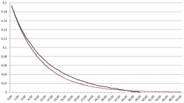
Some home brew measurements
I did some measurements today just to verify I didn't screw anything up while soldering this controller together. Attached is a picture of what I measured in black line and the blue/red line is the ideal logarithmic curve according to the excel file in this post. In the horizontal axis there's the 50 attenuation steps configured into the LDR. Vertical axis is the volts measured with DMM from the output terminals.
I used iPhone feeding the LDR controller by playing 1 kHz 0 dB test tone from Spotify (Audiolab: Audio Test Tones) with iPhone volume set to max. I measured only 0,193 V from the iPhone output, but hey, it's only iPhone.
The LDR controller was set to 20 kOhm nominal impedance and the next stage input impedance was set to 330 kOhm (my future Salas DCG3). I think the curves are matching quite closely and there's no bumps or other inconsistencies seen. I'm very happy with the results.
Attachments
Last edited:
pcb
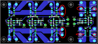
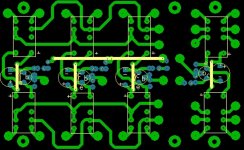
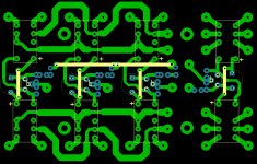
Hi
I have made my own pcb 5X8cm for my own relays Nais TXD2-L45 - 4.5V Latching DPDT that I had at my disposal.
the spots IN L+ IN L- and IN R+, IN R- go to the main controller in spots IN L ,LGND and IN R , RGND ?
The spots ATT L- ATT L+ and ATT R-ATT R+ from output relays where they are going;?
Hi
I have made my own pcb 5X8cm for my own relays Nais TXD2-L45 - 4.5V Latching DPDT that I had at my disposal.
the spots IN L+ IN L- and IN R+, IN R- go to the main controller in spots IN L ,LGND and IN R , RGND ?
The spots ATT L- ATT L+ and ATT R-ATT R+ from output relays where they are going;?
Attachments
Last edited:
Hi Zdr,
To swap R5 and R6 in the code, should I change the code like below??
#define PIN_EXT_R1 1 // port extender: relay 1
#define PIN_EXT_R2 2 // port extender: relay 2
#define PIN_EXT_R3 3 // port extender: relay 3
#define PIN_EXT_R4 6 // port extender: relay 4
#define PIN_EXT_R5 5 // port extender: relay 5
#define PIN_EXT_R6 4 // port extender: relay 6. Used for delay relay
#define PIN_EXT_BIAS 7 // port extender: BIAS
-----> #define PIN_EXT_R5 4
-----> #define PIN_EXT_R6 5
Confirmed, this is what needs to be done. Not sure why it didn't work for me before, probably messed up something else.
Anyway, I have found some bugs in OLED code, mainly related to text display and fonts. This has now been corrected, and I also added switch for AIO PCBs while I was at it. Same code now runs all PCBs.
#define AIO //** enables AIO PCB, comment out for original PCB
https://drive.google.com/drive/folders/0B74euvw8ey5JOENmRXNYUEtySVE
- Home
- Source & Line
- Analog Line Level
- Arduino based LDR volume and source selection controller