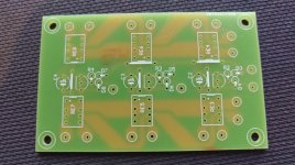
Taking for example the variable trimmer pot RT1, let's say pin 1 is at the top and goes to Bias, pins 2 (middle variable one) and 3 are shorted together and go to R5, C2, C14, R6 and R8.
Looking at the Eagle PCB routing, the Bias pin 1 next to the pot screw is shorted with the middle pin 2. Pin 3 goes to R5, C2, C14...
So the PCB drawing shorts pins 1 and 2 whereas the schematic shorts pins 2 and 3.
Have I misunderstood something?
Hi,
You are right, the schematic and the board are not coherent about the direction of the trimmer pots. But it doesn't matter in fact, it works the same either way!
The pin numbers you added to the schematic are wrong - the arrow points from pin 1 to pin 3. So both the schematic and the board short pins 1 and 2, but the orientation is not the same. It works the same because it's just a variable resistor.
Any possibility to obtain a fully assembled board? I'd be interested to go this route.
If the answer is no: what are alternative LDR boards? I am aware of the Tortuga Kit – anything else out there?
If the answer is no: what are alternative LDR boards? I am aware of the Tortuga Kit – anything else out there?
Any possibility to obtain a fully assembled board? I'd be interested to go this route.
If the answer is no: what are alternative LDR boards? I am aware of the Tortuga Kit – anything else out there?
There is wapo54001's LDR attenuator here on diyAudio, but without channel switching. http://http://www.diyaudio.com/foru...70381-precision-led-ldr-based-attenuator.html
I am using IDE 1.6.5 in case that matters?
This is the cause you had problems with the remote - the newer Arduino IDE has changed the way "pulseIn" works. I developed the code using IDE 1.6.1.
So, please download version 1.6.1 from here: https://www.arduino.cc/en/Main/OldSoftwareReleases#previous
I have updated the project with the latest information.
Changelog:
- updated wrong pin header quantity in the BOM
- added LCD contrast adjustment information
- measuring the LDR R values and the +5v supply during setup are now optional (but recommended)
- the code is to be compiled with Arduino IDE v1.6.1 only!
Changelog:
- updated wrong pin header quantity in the BOM
- added LCD contrast adjustment information
- measuring the LDR R values and the +5v supply during setup are now optional (but recommended)
- the code is to be compiled with Arduino IDE v1.6.1 only!
Attachments
Vincent, presumably, if you manually programmed the response to emulate a log pot, it could be tweaked to have a more linear attenuation? I have some ideas that would work better with a linear behaviour I'd like to experiment with.
I'll start looking at the code to see if I can figure it out, but if you know for a fact it's not possible (one would have to start from scratch), it would be great to know.
Thanks")
I'll start looking at the code to see if I can figure it out, but if you know for a fact it's not possible (one would have to start from scratch), it would be great to know.
Thanks
Vincent, presumably, if you manually programmed the response to emulate a log pot, it could be tweaked to have a more linear attenuation?
It's very easy to do: in the function float getAttFromStep(byte step) , line 908, the local variable "p" contains the linear attenuation.
So you comment out the lines 910 to 915 and add the line:
return p;
You'll get a linear attenuation this way.
I received the input boards from ShenZhen2U a few days ago and have ordered parts...
Nice! Keep us updated about your project!
Awesome. Thanks!It's very easy to do: in the function float getAttFromStep(byte step) , line 908, the local variable "p" contains the linear attenuation.
So you comment out the lines 910 to 915 and add the line:
return p;
You'll get a linear attenuation this way.
Hi
Am trying to build this LDR Controller without IO board to start with and almost there
The Attenuator has 5 pins (2 on one side, 3 on other side), the header pin goes to it has 4 pins, which ones goes where?
Am of the view that
1. ENC SWITCH and ENC GND goes to 2 pin side
2. ENC CCW and ENC CW goes to 1st and 3rd pin on 3 pin side. The middle pin goes to Ground??
Can someone advise?
Thanks
Last edited:
Thanks tfboy, i did the same and progressing with measurements.
At Adjust Bias option, LSE and HSE i could measure around 700k using corresponding trimmers but LSH and RSH am not able to.
The multimeter showing 1 irrespective of resistance level selection from 200ohm to 2M, despite adjusting corresponding trimmers (RT4, RT2) Is this normal or am I doing it wrong? Am measuring without input/output.
Hi
The Attenuator has 5 pins (2 on one side, 3 on other side), the header pin goes to it has 4 pins, which ones goes where?
Am of the view that
1. ENC SWITCH and ENC GND goes to 2 pin side
2. ENC CCW and ENC CW goes to 1st and 3rd pin on 3 pin side. The middle pin goes to Ground??
Hello,
Yes, you got it right, ENC GND goes to the middle of the three pins on the rotary encoder and also to one of the two pins (doesn't matter which one of the two). You will see that on the controller schematic.
On the encoder, the two pins are the switch: SW - GND; the three pins are CW - GND - CCW.
At Adjust Bias option, LSE and HSE i could measure around 700k using corresponding trimmers but LSH and RSH am not able to.
The multimeter showing 1 irrespective of resistance level selection from 200ohm to 2M, despite adjusting corresponding trimmers (RT4, RT2) Is this normal or am I doing it wrong? Am measuring without input/output.
Not normal, there must be an error somewhere...
Thanks Vincent77,
I will first for sure check all connections for dry solder joints..
any tips on where to begin debugging eg., some voltage at different points etc.,
Do i need to solder right/left input connections for bias and measurements? I dont listen any activity/clicking of the 3 relays on the board, may be this rings a bell?
I have checked the power supply they are at right voltages 12v, 8v and 12v. they are connected at correct headers.
I will first for sure check all connections for dry solder joints..
any tips on where to begin debugging
eg., some voltage at different points etc.,Do i need to solder right/left input connections for bias and measurements? I dont listen any activity/clicking of the 3 relays on the board, may be this rings a bell?
I have checked the power supply they are at right voltages 12v, 8v and 12v. they are connected at correct headers.
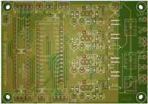
You do not need to solder the left/right output connections (I mean the attenuator connections), it works either way.
It is normal that the relays do not click during bias adjustment - they only click right after you power on the module and also at the beginning of the calibration procedure.
You could measure the voltage at the red points on this image:
It is normal that the relays do not click during bias adjustment - they only click right after you power on the module and also at the beginning of the calibration procedure.
You could measure the voltage at the red points on this image:
Attachments
- Home
- Source & Line
- Analog Line Level
- Arduino based LDR volume and source selection controller