Hi everyone,
I've always heard that when making an adapter that goes from XLR to RCA, you the standard way of wiring it is to tie pins 1(ground) and 3(cold) together like this: How to Wire an XLR to an RCA Connector
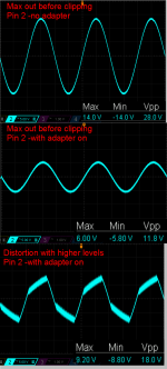
When using such an adapter though, it limits the maximum output of the preamp by almost a third.
This attached picture shows the maximum voltage out of the hot(pin 2) line without the adapter and then with the adapter. The adapter that ties pins 1 and 3 together causes a lot of distortion past ~6Vpk.
Does anyone know why this is the common way to adapt XLR to RCA if it causes this problem?
I've always heard that when making an adapter that goes from XLR to RCA, you the standard way of wiring it is to tie pins 1(ground) and 3(cold) together like this: How to Wire an XLR to an RCA Connector
When using such an adapter though, it limits the maximum output of the preamp by almost a third.
This attached picture shows the maximum voltage out of the hot(pin 2) line without the adapter and then with the adapter. The adapter that ties pins 1 and 3 together causes a lot of distortion past ~6Vpk.
Does anyone know why this is the common way to adapt XLR to RCA if it causes this problem?
Attachments
It depends on the whether the source is more or less floating (high common-mode output impedance, for example a transformer-coupled output) or not (low common-mode output impedance, for example two amplifier stages driven in antiphase, one of which drives pin 2 and the other pin 3).
With a source with floating output you need to ground pin 3 to stop the source from floating. When it doesn't float in the first place, you have to keep pin 3 open to ensure you don't short circuit anything.
With a source with floating output you need to ground pin 3 to stop the source from floating. When it doesn't float in the first place, you have to keep pin 3 open to ensure you don't short circuit anything.
Say we're talking about an 8pin dual package op amp with 2 inverting buffers to get the hot and cold out. There is an AC coupling cap and then 100 ohm resistor to isolate the op amp from the capacitance of the output cable.
Is leaving one side of the op amp floating bad in this case?
Wouldn't it make more sense for the adapter and put a load resistor between pins 1 and 3 so the output amp isn't floating anymore if this is a bad thing?
I guess because this thing is distorting badly with pin 1 and 3 tied together it's common-mode output impedance is high?
Would it make sense to put a resistor load from pin 3 to ground then?
Hi,
AFAIK its the other way round, 1 & 3 together for RCA to XLR.
Shorting an active output is always a bad idea, leave 3 open.
rgds, sreten.
Some professional equipment is setup (on purpose) such that providing a pin 1-3 short on the output increases the gain available on pin 2. (The Behringer equipment for example.) However, I agree that it's probably preferable to not have the pin 1-3 connection.
Shredhead, I would perform surgery on your adaptors to remove the pin 1-3 connection. That will most likely eliminate your distortion. If you have enough gain then you're all set. Limiting your preamp maximum output is not necessarily a bad thing. This "floating" output on pin 3 will not be an issue at all.
FYI, a lot of source equipment with balanced XLR outputs doesn't even have signal on pin 3. Just a resistor to ground with a value equivalent to the source resistance on pin 2 to create the balanced source impedance.
Cheers,
Dave.
Say we're talking about an 8pin dual package op amp with 2 inverting buffers to get the hot and cold out. There is an AC coupling cap and then 100 ohm resistor to isolate the op amp from the capacitance of the output cable.
Is leaving one side of the op amp floating bad in this case?
Wouldn't it make more sense for the adapter and put a load resistor between pins 1 and 3 so the output amp isn't floating anymore if this is a bad thing?
I guess because this thing is distorting badly with pin 1 and 3 tied together it's common-mode output impedance is high?
Would it make sense to put a resistor load from pin 3 to ground then?
In this case I'd leave pin 3 open. Both op-amps produce a voltage referred to ground, so it doesn't float with respect to ground (not at the signal frequencies, that is).
No, Pin1 goes to Chassis. that will be at the XLR end of your interconnect cable..................I've always heard that when making an adapter that goes from XLR to RCA, you the standard way of wiring it is to tie pins 1(ground) and 3(cold) together like this: How to Wire an XLR to an RCA Connector................
Pins 2 & 3 are the Signal Pins.
There will be a voltage difference (the Signal voltage) between Pin2 and Pin3. Your Receiver will read this voltage DIFFERENCE and amplify it.
But there is the Balanced impedance source to be checked.
Will it accept connecting Pin3 to Audio Ground in the Receiver?
Most Balanced Impedance Sources will accept this connection (Pin3 to unbalanced Audio Ground).
Pin 1 Revisited
Sound System Interconnection
see 1, 2, 5, 6, 7, 8, 11, 12, 13, 14, 17, 18 and 23 all show balanced to unbalanced and all show the shield connected to chassis at the balanced end.
All show the shield NOT connected to either of the the signal wires at any end.
opamps take a signal difference input and send a signal difference output.Hi DF96 and AndrewT nice to see you guys again.
Op amps are stable with their outputs floating right? Cause if so, I don't see myself ever connecting pins 1 and 3 for an adapter again.
We often only see the HOT signal input and the HOT signal output because of the universal adopting of the "hidden" signal ground as standard layout/schematic.
But the hidden signal ground is the other half of the input signal and the output signal.
Add that signal ground back in.
Now you will find that the output can NEVER be floating. The Output is referenced to the input via the SAME Signal Ground. It is not floating.
Oh, an op-amp output certainly CAN be floating. ") Or at least in a state that allows it to drift to one of the voltage rails. I don't believe that's the case here with shredheads inverting buffer setup.
Or at least in a state that allows it to drift to one of the voltage rails. I don't believe that's the case here with shredheads inverting buffer setup.
The "floating" issue is being confused here. Even if you leave pin 3 unconnected, that op-amp output is not floating.....it's just unconnected.
To get the output to "float" you would need to be running it with the inputs unconfigured in some way. Normally, with an unused opamp (or section) you would tie the output back to the inverting input and take the non-inverting input to ground via a resistor.
Cheers,
Dave.
Or at least in a state that allows it to drift to one of the voltage rails. I don't believe that's the case here with shredheads inverting buffer setup.The "floating" issue is being confused here. Even if you leave pin 3 unconnected, that op-amp output is not floating.....it's just unconnected.
To get the output to "float" you would need to be running it with the inputs unconfigured in some way. Normally, with an unused opamp (or section) you would tie the output back to the inverting input and take the non-inverting input to ground via a resistor.
Cheers,
Dave.
- Status
- This old topic is closed. If you want to reopen this topic, contact a moderator using the "Report Post" button.
- Home
- Source & Line
- Analog Line Level
- XLR to RCA adapter causes gross amounts of distortion...