Hello,
I just got a Behringer cx2300 crossover and I was thinking of replacing the electrolytic capacitors.
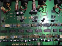
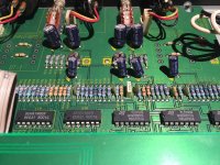
The unit looks decent. I see no apparent repairs, although the blown fuse has been bypassed with a wire :/
The regulators seem stock, encased in plastic. No metal tabs on them.
My issue is that there are many 22uF capacitors in the circuit, in the signal path.
I could replace them with Wima caps, the MKS2 series has 10uF values (with 5mm pin distance), and I'd have to parallel them but this will quickly get very expensive as there are about 32 x 22uF caps in this crossover. 64 Wima caps would be too expensive and I don't think they would fit anyway.
Is there a way to redesign the circuit using 10uF caps (instead of the 22uF ones) and different values resistors?
I would appreciate any detail on this as I would like to remove as more electrolytic capacitors as possible from the signal path.
I could also bypass the output ones as I have input caps in my amplifier.
I just got a Behringer cx2300 crossover and I was thinking of replacing the electrolytic capacitors.
The unit looks decent. I see no apparent repairs, although the blown fuse has been bypassed with a wire :/
The regulators seem stock, encased in plastic. No metal tabs on them.
My issue is that there are many 22uF capacitors in the circuit, in the signal path.
I could replace them with Wima caps, the MKS2 series has 10uF values (with 5mm pin distance), and I'd have to parallel them but this will quickly get very expensive as there are about 32 x 22uF caps in this crossover. 64 Wima caps would be too expensive and I don't think they would fit anyway.
Is there a way to redesign the circuit using 10uF caps (instead of the 22uF ones) and different values resistors?
I would appreciate any detail on this as I would like to remove as more electrolytic capacitors as possible from the signal path.
I could also bypass the output ones as I have input caps in my amplifier.
Attachments
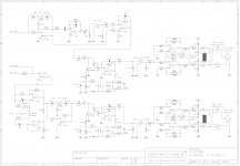
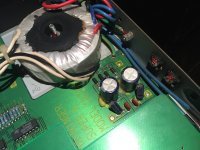
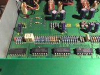
The unit uses a simple regulated supply with 7815/7915 devices.
The positive rail is at +15VDC but the negative sits at about -14.6VDC. The regulators are incased in plastic, no metal tabs.
Lots of quad op-amps, 12 of them. And a dual JRC 4580.
I don't know exactly what kind of op amps the BE037 are but I might replace them for TL074. They might have been replaced at some point (the existing TL074) as I've seen some other pictures of this unit with more Behringer branded opamps (and fewer tl074). Or they might be from the factory and they installed them at random.
I might replace the small white film caps with some Wima caps. There are some crazy values like 1.8nF and 5.6nF that I might have some problems with.
But the most important thing would be to get rid of as many electrolytic capacitors as possible, and up the ps ones a bit (or maybe more if recommended).
I might use some Panasonic FM/FR as I have easy access to those and are cheap.
Also I'm thinking of getting a DI4000 unit as it has 4 transformers that fit on my board. I have the footprint and it is shunted by 0R resistors.

They run pretty cheap for what they offer.
But at the moment I need to focus on replacing the electrolytic caps.
The positive rail is at +15VDC but the negative sits at about -14.6VDC. The regulators are incased in plastic, no metal tabs.
Lots of quad op-amps, 12 of them. And a dual JRC 4580.
I don't know exactly what kind of op amps the BE037 are but I might replace them for TL074. They might have been replaced at some point (the existing TL074) as I've seen some other pictures of this unit with more Behringer branded opamps (and fewer tl074). Or they might be from the factory and they installed them at random.
I might replace the small white film caps with some Wima caps. There are some crazy values like 1.8nF and 5.6nF that I might have some problems with.
But the most important thing would be to get rid of as many electrolytic capacitors as possible, and up the ps ones a bit (or maybe more if recommended).
I might use some Panasonic FM/FR as I have easy access to those and are cheap.
Also I'm thinking of getting a DI4000 unit as it has 4 transformers that fit on my board. I have the footprint and it is shunted by 0R resistors.
They run pretty cheap for what they offer.
But at the moment I need to focus on replacing the electrolytic caps.
Attachments
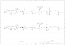
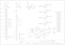
I added some comments on the crossover frequency setting.
To switch the range you have to brake some traces and make others but should be simple looking in the schematics.
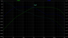
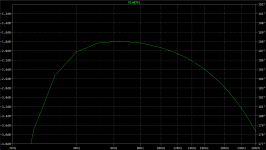
Also I plotted the frequency response with both 22uF original values and 10uF values (I replaced all 22uF in the schematic).
Seems like a small increase in the lower part, sub 10Hz. I don't mind that at all.
If there aren't any obvious reasons that I don't understand then it seems I can replace them with 10uF value.
To switch the range you have to brake some traces and make others but should be simple looking in the schematics.
Also I plotted the frequency response with both 22uF original values and 10uF values (I replaced all 22uF in the schematic).
Seems like a small increase in the lower part, sub 10Hz. I don't mind that at all.
If there aren't any obvious reasons that I don't understand then it seems I can replace them with 10uF value.
Attachments
Last edited:
Most of the 22uF are feeding resistances around 10k. One feeds only 2k, but even then the LF rolloff will be 3.6Hz so quite low. As there will be very little signal voltage across the 22uF caps they cannot do any harm.
By all means replace them if it makes you feel better. If the replacements are physically larger then there will be an increased risk of stray capacitive coupling.
By all means replace them if it makes you feel better. If the replacements are physically larger then there will be an increased risk of stray capacitive coupling.
That's what I saw as well and it looks ok.
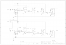
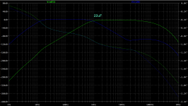
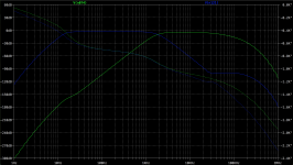
I see that in this design there's a 1dB rolloff from 7KHz to 20KHz. With the xover point at 2KHz or so.
Is there something that I could do to address this issue? This is with stock values by the way. But it doesn't make any difference for the high end if I use 10uF values.
What exactly creates that in the circuit?
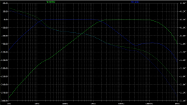
Attachments
There's also the last thing that bothers me, the 220uF/6V electrolytic capacitor. What is it's purpose in that spot?
I can leave the feedback network values stock by removing the limiting circuit. I don't need this function at all.
I can leave the feedback network values stock by removing the limiting circuit. I don't need this function at all.
Attachments
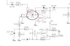
It is a coupling capacitor. When the FET imposes a low resistance on the signal (high attenuation) then the 220uF works with the 68R to maintain LF response. With the FET missing the cap does not do very much, but it does no harm either.
Why do you have such a dislike of electrolytics? I'm guessing that your questions imply that this does not arise from a careful consideration of their exact use in the various circuit positions. Wait, don't tell me - you read on a website that electrolytics kill good sound?
Why do you have such a dislike of electrolytics? I'm guessing that your questions imply that this does not arise from a careful consideration of their exact use in the various circuit positions. Wait, don't tell me - you read on a website that electrolytics kill good sound?
A lot of the time replacing the signal coupling electrolytic caps in this sort of equipment will yield very little in audible benefits.
I have found that with most of this sort of equipment - which is definitely built cheaply, that real audible benefits are achieved by looking at the op amp voltage rails and decoupling. Something as simple as adding a quality pair of 100uF 16V caps to the 15V voltage rails will give the whole unit a lift.
I have found that with most of this sort of equipment - which is definitely built cheaply, that real audible benefits are achieved by looking at the op amp voltage rails and decoupling. Something as simple as adding a quality pair of 100uF 16V caps to the 15V voltage rails will give the whole unit a lift.
Well for starters connecting the crossover in my system felt like a blanket has been put over the speakers. That's one thing that I'm trying to correct. Sure, it may be from different other sources but for starters I suspect the electrolytic capacitors.
Then there's the fact that from all types of capacitors, the electrolytic ones age the worst.
They also are not very precise values, even if they work with their rating in my circuit.
I will also look at the power supply but that is a small affair compared to 40+ caps in the signal path")
I would prefer to do this from a reliability point of view, and hopefully the blanket will come off the speakers.
Then there's the fact that from all types of capacitors, the electrolytic ones age the worst.
They also are not very precise values, even if they work with their rating in my circuit.
I will also look at the power supply but that is a small affair compared to 40+ caps in the signal path
I would prefer to do this from a reliability point of view, and hopefully the blanket will come off the speakers.
Well at least you are using your ears!
Panasonic FM caps are useful as they come in a good range of sizes.
I would still look at the voltage rails first. Adding some caps and looking at the decoupling side of things just might remove some of those blankets!
Without getting this right you may not here any improvements from your other upgrades.
It might be a bit difficult to add 100uF caps to the op amps. I could add a 100nF cap across the rails on each op amp but adding 100uF on each rail at each op-amp is a bit tricky. The power supply lines are on the backside of the board. I need to find some grounds near the op amps and do some stitching with wires.
Is that what you meant?
Is that what you meant?
Why?Trileru said:Sure, it may be from different other sources but for starters I suspect the electrolytic capacitors.
They don't need to be. As coupling caps with an LF rolloff mostly around 1Hz their exact value is of little consequence.They also are not very precise values
After a few years on this and other forums I have found that "re-capping" is a good way to significantly degrade reliability, as in "I changed all the caps, and now it doesn't work. Can someone please help?".I would prefer to do this from a reliability point of view
The main cause of a "blanket" is a significant HF rolloff. This may be a design feature (to provide 'smoothness'). Unlikely to be caused by electrolytics. Your simulation shows an HF rolloff, so it is caused by the circuit not the components.hopefully the blanket will come off the speakers
Re-capping can help in some cases - mostly due to the effect of replacing an aged component with a new one. But audibly I would expect very little change.
The real savings will have been made in the PSU & decoupling where the bare minimum to get the circuit to work will have been used.
I have upgraded many bits of my rack gear including Behringer compressors, and sorting out the voltage rail decoupling makes an audible difference.
If you go overboard with the voltage rail capacitors add some protection diodes across the voltage regulators to stop reversed current flows when you switch off.
Last edited:
Why?
For starters because this is a 1995 unit. That's 20 years.
The unit has Samxon GR series capacitors (it's the same as CapXon GR). These are general purpose 85 degrees C rated for 2000 hours. Given a conservative of 5 hours a week it works out at almost 5000 hours, so they are a good bit over their lifetime rating. Given the state that this unit is in I can safely presume that the capacitors are the weakest part in it.
This is a sound technical deduction, nothing far reaching.
Yes, electrolytic caps can go way longer than this with no apparent issues, but given the fact that this unit is aimed at pro use (lower end for sure), then it makes even more sense to suspect/replace the electrolytic capacitors. For all I know this unit might have been used for gigs for way more than 5 hours/week.
This isn't a top of the line hi-fi unit, it makes sense it's been heavily used and abused (considering the fact that the blown fuse has been bypassed by a wire).
I also said that I understand that it's not of much consequence that they are not precise in value, but I usually like tight tolerances for my personal gear.
I understand that sometimes replacing many capacitors in some units can mess things up, especially where some sensible characteristics like the higher ESR of capacitors are designed into the circuit may screw things up. Low esr caps in regulated supplies might throw them into oscillations etc.
And lastly the high freq roll off is of 1dB from 6KHz to 20KHz. I don't think that is what's caused the change in sound but ... it may very well be.
I very much understand your frustration with the whole capacitor business. I myself don't believe in capacitor "sound", just in their characteristics.
Wima MKS2 is the only type of film cap that has 10uF values with 5mm pin distance and that suits me well as I usually prefer to not be bothered with electrolytic capacitors and their bad reputation (in time). It's not like I want to install teflon capacitors into this thing.
The 'blanket' will be noisy power supplies - so what Xoc1 said. Except instead of 100nF across the quad opamps' power pins I'd go all-out and fit a low ESR 'lytic there, at least 470uF on each.
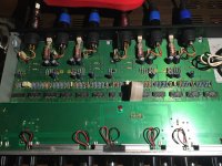
The negative rail is at -14.6VDC or so. I will replace that regulator but I need to add a sil-pad as the original ones are encased in plastic.
For how much can I up the 1000uF existing ones?
There's only one 10uF cap across both rails near one op-amp. I think from there the ps traces go to each op amp.
Re-capping can help in some cases - mostly due to the effect of replacing an aged component with a new one. But audibly I would expect very little change.
The real savings will have been made in the PSU & decoupling where the bare minimum to get the circuit to work will have been used.
I have upgraded many bits of my rack gear including Behringer compressors, and sorting out the voltage rail decoupling makes an audible difference.
If you go overboard with the voltage rail capacitors add some protection diodes across the voltage regulators to stop reversed current flows when you switch off.
There are 13 op amps
I can add a cap across the rails on each one.Should I try and figure out a way to add 100uF on each rail at each op-amp?
- Status
- This old topic is closed. If you want to reopen this topic, contact a moderator using the "Report Post" button.
- Home
- Source & Line
- Analog Line Level
- Behringer CX2300 replace caps (values change)