PMA said:Have tried many times, it is worse than average opamp.
in what regard is it worse?
Many people on this forum (myself included) have designed and built very simple discrete I/V stages to replace the multitude of op-amps usually employed in CDP's and have found the simpler circuits sound superior.
The output stage of my design is essentially the same as the simple buffer described here and sonically it beats the op-amp version in every way.
I say keep it simple, an op-amp is complete overkill for this application.
The output stage of my design is essentially the same as the simple buffer described here and sonically it beats the op-amp version in every way.
I say keep it simple, an op-amp is complete overkill for this application.
Tougher Buffers
"A plagiarized version of the LH0063C 'ultra damn fast buffer'."
See post #38 this thread.
A couple of notes on the Jfet BJT buffer shown:
Q5 is shown with the collector and emitter leads swapped and must be reversed.
The circuit has a lot of DC offset unless the Idss of J1 and J3 as well as J2 and J4 are matched. Actually they should their drain currents should match when the magnitude of the gate to source voltage is around 0.75 volts for both N and P channel jfets. Thermally couple J1 and J3 so that they are at the same temperature.
The current source Jfet J4 should be made adjustable with a pot for source degeneration such that it's current can be made larger or smaller so than the current through J2. Make both of these a N channel jfet. Sort for Idss of above 4 ma and use the greater Idss jfet for J4.
I wound use a series resistor of 25 to a 100 ohms on the output for driving capacitive loads like cables.
Put something around 100 to 500 ohm for gate resistors on J1 and J2.
Put a low ESR 27 to 100uF cap across the collector to emitter of Q1
It looks like it might make a pretty good buffer with these chages. I have not built this one but I may try it.

The circuit which started it all, for me...
Thanks for all the inputs, and I now at least know for certain that this two-transistor thing is worth trying. But some of you have wondered why one should try something so primitive, when an opamp will perform better in every respect. So I thought I'll tell you how Angshu and I started on this path.
I had seen a circuit of a unity-gain buffer (complete with the -0.7V output DC offset) in an issue of Elektor two decades old. This buffer was added as an afterthought by their designers to a discrete preamp which was (by those days' standards) top of the line, which had been published in earlier issues. That preamp was called the Prelude (anyone know it?)
I assumed, correctly or naively, that since this buffer is for the Prelude, it must be superb in cleanness of its sound. I passed it on to Angshu, who simulated it and was unimpressed. That's when he said that the two-transistor alternative would probably perform better, and put it together on his simulator and ran some tests. That's what started us on the long road of opamps-versus-simple-discretes.")
What do you guys think of the Elektor Prelude buffer? It appeared in the Indian reprint of the mag in June 1983; the UK edition must have carried it a few months earlier. The brief description which went with it is reproduced in full below:
Tarun
Thanks for all the inputs, and I now at least know for certain that this two-transistor thing is worth trying. But some of you have wondered why one should try something so primitive, when an opamp will perform better in every respect. So I thought I'll tell you how Angshu and I started on this path.
I had seen a circuit of a unity-gain buffer (complete with the -0.7V output DC offset) in an issue of Elektor two decades old. This buffer was added as an afterthought by their designers to a discrete preamp which was (by those days' standards) top of the line, which had been published in earlier issues. That preamp was called the Prelude (anyone know it?)
I assumed, correctly or naively, that since this buffer is for the Prelude, it must be superb in cleanness of its sound. I passed it on to Angshu, who simulated it and was unimpressed. That's when he said that the two-transistor alternative would probably perform better, and put it together on his simulator and ran some tests. That's what started us on the long road of opamps-versus-simple-discretes.
What do you guys think of the Elektor Prelude buffer? It appeared in the Indian reprint of the mag in June 1983; the UK edition must have carried it a few months earlier. The brief description which went with it is reproduced in full below:
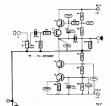
The description was brief because it was not a full construction article... just an add-on note with the PCB layout and the schematic. Is this circuit state-of-the-art for 1983, but has been trounced by more recent opamps and discretes since then?The circuit illustrated here can be used as buffer for the 100mV inputs of the Prelude and as output buffer for the tape recording and auxilliary outputs. The actual emitter follower consists of a 'super transistor', formed by the cascode T1 and T2. Capacitor C2 ensures that the base of T2 follows the emitter voltage of T1, which is very favourable for its modulation 'behaviour'. The supply for the emitter follower is provided by a current source, which is also connected as cascode (T3 and T4); this increases the (already high) linearity of the emitter follower considerably.
Tarun
Attachments
Re: The circuit which started it all, for me...
The Elektor super follower may be considered epoche-specific, but it nevertheless works well.
Especially I can't see why the simulation didn't impress.
For 5kHz input I get these numbers:
@ 1 V rms
K2 0.000443%
K3 0.000004%
@ 3 V rms
K2 0.001334%
K3 0.000042%
K4 0.000001%
Regards,
Peter Jacobi
tcpip said:[...]
I assumed, correctly or naively, that since this buffer is for the Prelude, it must be superb in cleanness of its sound. I passed it on to Angshu, who simulated it and was unimpressed. That's when he said that the two-transistor alternative would probably perform better, and put it together on his simulator and ran some tests. [...]
The Elektor super follower may be considered epoche-specific, but it nevertheless works well.
Especially I can't see why the simulation didn't impress.
For 5kHz input I get these numbers:
@ 1 V rms
K2 0.000443%
K3 0.000004%
@ 3 V rms
K2 0.001334%
K3 0.000042%
K4 0.000001%
Regards,
Peter Jacobi
Tarun,
I've not seen this Elektor design before; it is a most impressive topology.
There are two sources of non-linearity in the conventional emitter follower with active load. The Vbe changes with signal as the Vce changes, and this is a source principally of H2. If the EF enjoys constant current operation courtesy of the active load then any variation on Vce will affect Vbe and thus keeping the Vce constant, as the Elektor circuit does with a bootstrap, is VERY clever.
The second source is actually the same mechanism, though it affects Ic. As the Vce varies with signal, the current through the device will change since the reference voltage is essentially fixed. This can be stabilized by giving the CCS a constant Vce; best done with a cascode. The way in which this is implemented is simple and elegant.
So, on balance, I would say that since the two primary non-linearities of the conventional EF are here eliminated, it should sound damn good.
And, it's pretty simple.......
Cheers,
Hugh
Please be so kind and have look at this modification of the Elektor circuit:
PDF: http://www.linearaudio.de/scratch/elektor-follower-mod.pdf
LTSpice: http://www.linearaudio.de/scratch/elektor-follower-mod.asc
Plus: will save endless debates about which condensator sounds best as C2
Minus: will be trashed by both the BJT-only and the FET-only faction
At least the SPICE faction is happy: Sims see -140dB THD for 3Vrms (and yes, I know for what the "A" in "CAD" stands).
My knowledge of JFETs is basic, to put it mildly, but I've already got it from another thread, that the BF245 isn't good for small signal audio. I've selected it, because the models are in reasonable agreement with the datasheets. Alternative choices are most welcome.
Regards,
Peter Jacobi
(Links corrected)
Re: Re: The circuit which started it all, for me...
Try to run the simulation with a reasonable load (i.e. 10K) and the picture will change.
x-pro
pjacobi said:
The Elektor super follower may be considered epoche-specific, but it nevertheless works well.
Especially I can't see why the simulation didn't impress.
For 5kHz input I get these numbers:
@ 1 V rms
K2 0.000443%
K3 0.000004%
@ 3 V rms
K2 0.001334%
K3 0.000042%
K4 0.000001%
Regards,
Peter Jacobi
Try to run the simulation with a reasonable load (i.e. 10K) and the picture will change.
x-pro
Re: Re: Re: The circuit which started it all, for me...
Hi x-pro, All,
Generally speaking: Yes, of course. You'll need a comfortable ratio of Iq to output current, to get these low numbers.
Changing the output R to 10k, you can still drive 1Vrms:
1Vrms / 10k load / 1mA Iq
K2 0.013430%
K3 0.000758%
K4 0.000048%
K5 0.000003%
But for driving 3Vrms, you better change Iq to 5mA by changing R10 to 150. Then the numbers are fine again:
3Vrms / 10k load / 5mA Iq
K2 0.001399%
K3 0.000051%
K4 0.000002%
Lacking the necessary measurement equipment, I would really like to hear reports about the performance of this circuit in the real world.
Regards,
Peter Jacobi
Hi x-pro, All,
x-pro said:Try to run the simulation with a reasonable load (i.e. 10K) and the picture will change.
Generally speaking: Yes, of course. You'll need a comfortable ratio of Iq to output current, to get these low numbers.
Changing the output R to 10k, you can still drive 1Vrms:
1Vrms / 10k load / 1mA Iq
K2 0.013430%
K3 0.000758%
K4 0.000048%
K5 0.000003%
But for driving 3Vrms, you better change Iq to 5mA by changing R10 to 150. Then the numbers are fine again:
3Vrms / 10k load / 5mA Iq
K2 0.001399%
K3 0.000051%
K4 0.000002%
Lacking the necessary measurement equipment, I would really like to hear reports about the performance of this circuit in the real world.
Regards,
Peter Jacobi
It doesn't sim possible.............
"Sims see -140dB THD for 3Vrms"
Doesn't this strike anybody as odd? Do you think this is even within two orders of magnitude of the real circuit. I really can't understand why people talk about simulating distortion with Spice. I guess it is easier than actually having to build something and measure it, or god forbid, listen to it. Spice is a nice design tool. I use it for lot's of stuff. But not for predicting distortion. Go actually measure something and you will find out.
PS There is this rumor floating around the low measured distortion doesn't always result in the best sounding circuits. It's been floating around for at least the last two decades in fact ...............
Re: It doesn't sim possible.............
No.
Yes.
There was a claim, that the Elektor circuit was inferior to or at least not better than the two transistor version - in SPICE simulation. I countered this claim.
I would be most interested in measurement results and hearing tests, but I have no lab and no golden ears (even slightly impaired hearing).
I am still interested in comments on this mod:
http://www.linearaudio.de/scratch/elektor-follower-mod.pdf
and advise, which JFETs to use.
Best Regards,
Peter Jacobi
Fred Dieckmann said:"Sims see -140dB THD for 3Vrms"
[...] Do you think this is even within two orders of magnitude of the real circuit.
No.
Fred Dieckmann said:I guess it is easier than actually having to build something and measure it, or god forbid, listen to it.
Yes.
Fred Dieckmann said:Spice is a nice design tool. I use it for lot's of stuff. But not for predicting distortion. Go actually measure something and you will find out.
There was a claim, that the Elektor circuit was inferior to or at least not better than the two transistor version - in SPICE simulation. I countered this claim.
I would be most interested in measurement results and hearing tests, but I have no lab and no golden ears (even slightly impaired hearing).
I am still interested in comments on this mod:
http://www.linearaudio.de/scratch/elektor-follower-mod.pdf
and advise, which JFETs to use.
Best Regards,
Peter Jacobi
I hope that is not the whole circuit.....
As Drawn......... Large DC offset. Also there should be a filter cap across R2 to filter supply noise from the reference voltage for the current source. You may not gain that much sonically or measurement wise from cascoding follower Q1. Many designers feel that followers sound best without cascodes. Voltage references for the cascode transistors that move with signal often don't sound as good as fixing the reference with respect to ground although the might measure better. The details in implementation of a topology are as important as the basic topolggy itself.
Fets for current sources:
http://www.vishay.com/document/70596/70596.pdf
Hi Fred, All,
Thanxalot for reference and judgement.
Yes, I was carelessly omitting "some details" in the circut.
Best Regards,
Peter Jacobi
Fred Dieckmann said:Re: I hope that is not the whole circuit.....
[...]
Thanxalot for reference and judgement.
Yes, I was carelessly omitting "some details" in the circut.
Best Regards,
Peter Jacobi
Will get you the layout
From what I remember, the PCB was about three inches by one inch, and had a stereo buffer circuit, and was simple enough for (even) me to make a simple layout using My Favourite Layout Editor. You still want the original layout? Just asking...
Tarun
Certainly can... just have to remember to fish out the old copy of the magazine. And even after I do that, the image from 21-year-old slightly yellowing paper may not be good enough for a direct photo etch. Please send me reminder email if I don't post the layout in the next two or three days?buchignani said:Any chance you could post the PCB layout image on this circuit?
From what I remember, the PCB was about three inches by one inch, and had a stereo buffer circuit, and was simple enough for (even) me to make a simple layout using My Favourite Layout Editor. You still want the original layout? Just asking...
Tarun
- Status
- This old topic is closed. If you want to reopen this topic, contact a moderator using the "Report Post" button.
- Home
- Source & Line
- Analog Line Level
- Simple discrete unity gain buffer