I recently bought one of these things to use as a pre-amp for my car's homemade aux input since it needs a higher voltage than a typical smartphone can provide. Previously I used a Velleman kit preamp but the low frequency response was just atrocious. I've got the NE5532 board wired up but now I get a ton of alternator noise unless I have something plugged into it and playing audio, and even sometimes when playing audio. It's very, very loud, it drowns out the audio playing the times you can hear both. Never had this with the Velleman kit, there was a bit of noise at high volumes though.
At the moment I have it drawing power from the head unit's power input, would running a dedicated 12v wire and grounding it somewhere else solve the ground loop issue?
I'd also like to turn up the gain a bit more, I have the pot maxed out and it's still not loud enough. Is there a specific resistor I can change out to accomplish this? The instructions supplied with the board are in Chinese so that's out of the question.
Also, the power input on the board has 3 pins: +, -, and gnd. I connected the + and gnd, is that correct?
Sorry for the newbie questions, I'm just in a bit over my head since I'm not very well versed in audio electronics.
I feel like the bearer of bad news here...
The write up implies (and this would be normal for an opamp preamp) that the design runs on what are called "split or dual" supplies meaning it needs both a positive and a negative supply voltage. That is the -/+ of the specification and the markings on the pins.
We would have to see a circuit to advise how/if you could make it work on single rail (12 volt car supply). It would involve modifying the board and circuit though.
(Another good option... bit of cost, not much, is to use a 12 volt to -/+18 volt convertor to power the preamp. These are tiny block like modules with 5 pins. 0 and 12 volts to connect to the supply and it provides an isolated supply of -18, 0 and + 18 volts)
Also, the power input on the board has 3 pins: +, -, and gnd. I connected the + and gnd, is that correct?
That's not going to get it.
Without a schematic who knows what's going on, but you need a dual-rail supply, or more detailed modification of the existing amplifier, a virtual ground or (probably simplest) an amplifier intended for single-rail operation.
it is designed for a split + - supply
12 to + auto gnd to - and 47K from - and + on board to gnd on board
Then a 100uf/16 v cap from - on board to gnd on board
it should then work
That doesn't sound bad at all, so just to clarify you're saying connect 2 47k resistors to the gnd pin and the other end of each to + and - respectively? Is that the cause of all the ground loop noise or should I also connect the 12v and gnd like how I asked in the first post?
The instructions came with a diagram, let me see if I can find it.
EDIT: Couldn't find the instructions but I did find this with a bit of googling. Also found a thread with someone basically trying to do the same thing.
Last edited:
^ Its not that simple I'm afraid.
Another problem is that the positive supply input goes to a voltage regulator and so feeding 12 volts into the board before the reg will result in poor performance because the opamp will see way under that applied voltage.
We need to see the circuit to see how the opamp is configured and what the options are.
These are the DC DC convertors I meant. This is a 15 volt,
1PA1215S-WR - POWERPAX - 1W UNREG SIP SCP 12V IN / + - | CPC
I think we can assume that it's an attenuator fed into a non inverting amplifier with about 6x gain. You could veroboard something like that with a couple of cheap transistors very quickly and it would be much better suited to single supply and lower voltage.
As it's car audio distortion performance shouldn't really matter too much.
If you're getting alternator noise you might want to check your grounding.
As it's car audio distortion performance shouldn't really matter too much.
If you're getting alternator noise you might want to check your grounding.
I figured the pdf might be helpful, wouldn't hurt to post it. Would it be worth it for me to draw a schematic based on looking at the board? It seems simple enough.
The weird part is it works just fine apart from the noise, I'd expect it to not work at all if it needs both + and - voltages.
The weird part is it works just fine apart from the noise, I'd expect it to not work at all if it needs both + and - voltages.
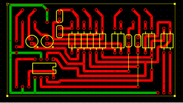
Ok I've traced out what I think is the full power circuit, is that enough?

The other end of C1 goes to the left channel output. The GND pin also goes to a whole bunch of other components, seems to be the main ground for the whole circuit. The last pin of v-in is '-', it didn't show up properly for some reason.
The other end of C1 goes to the left channel output. The GND pin also goes to a whole bunch of other components, seems to be the main ground for the whole circuit. The last pin of v-in is '-', it didn't show up properly for some reason.
Last edited:
I decided to map out the whole board, I had the NE5532 pins wrong in the previous picture.
http://i.imgur.com/TRMbDiS.jpg
For the audio out/in + is right channel and - is left, some limitation didn't let me do it properly. There might still be a mistake or two, but it looks right to me.
EDIT: Image isn't rescaling for some reason so I've made it a link.
http://i.imgur.com/TRMbDiS.jpg
For the audio out/in + is right channel and - is left, some limitation didn't let me do it properly. There might still be a mistake or two, but it looks right to me.
EDIT: Image isn't rescaling for some reason so I've made it a link.
Last edited:
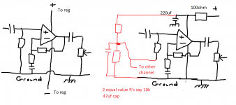
This is the sort of thing needed. This is what stocktrader was mentioning earlier. On the left is a standard dual rail and on the right that same design converted to single rail.
Now listen")
The caps shown at the input, at the output and in the feedback return are mandatory. They are the three caps I have shown. The regulators need to be removed from the board.
Pin 4 of the opamp needs linking to the original ground.
The 100 ohm plus cap is the new 12 volt feed into the board. That feeds onto pin 8.
The bias network in red provides a 'one half supply@ reference to bias the opamp. That can be shared between channels so you only need the one network.
As a check its all OK.
The DC voltage on pins 1 and 7 of the opamp should be around 6 to 7 volts give or take. There should be NO dc at the output or the inputs.
Now listen
The caps shown at the input, at the output and in the feedback return are mandatory. They are the three caps I have shown. The regulators need to be removed from the board.
Pin 4 of the opamp needs linking to the original ground.
The 100 ohm plus cap is the new 12 volt feed into the board. That feeds onto pin 8.
The bias network in red provides a 'one half supply@ reference to bias the opamp. That can be shared between channels so you only need the one network.
As a check its all OK.
The DC voltage on pins 1 and 7 of the opamp should be around 6 to 7 volts give or take. There should be NO dc at the output or the inputs.
Attachments
Awesome, can't thanks you guys enough for the help. It's still a bit early in the morning so what you've said just flew over my head but I'll come back to it later. For clarification, the bit that says 'to other channel' would connect to the other + channel through the same resistor/cap combination, correct?

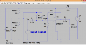
Nearly A bit of confusion over the feedback returns and bias supply. C10 needs to be across R9. Also R7 and R3 are returned to different points... however, there is a trick we can use to save two capacitors. We can return the feedback networks to the common bias point as long as the cap across the bias resistor is big enough.
So it looks like this. The bias network is on the left and will be shared between channels. You can see the circuit works well (within the limits of 12 volt supply) and how the gain is set by the two feedback resistors, the 68k and the 10k. The gain is (68000/10000) +1 which is 7.8
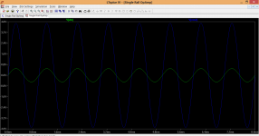
As the trace shows, that is exacty what we get. Vout is 7.8 times Vin.
A bit of confusion over the feedback returns and bias supply. C10 needs to be across R9. Also R7 and R3 are returned to different points... however, there is a trick we can use to save two capacitors. We can return the feedback networks to the common bias point as long as the cap across the bias resistor is big enough.So it looks like this. The bias network is on the left and will be shared between channels. You can see the circuit works well (within the limits of 12 volt supply) and how the gain is set by the two feedback resistors, the 68k and the 10k. The gain is (68000/10000) +1 which is 7.8
As the trace shows, that is exacty what we get. Vout is 7.8 times Vin.
Attachments
- Status
- This old topic is closed. If you want to reopen this topic, contact a moderator using the "Report Post" button.
- Home
- Source & Line
- Analog Line Level
- NE5532 preamp questions