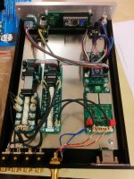
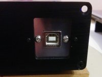
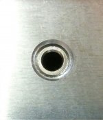
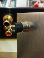
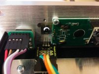
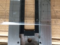
Continue tinkering with the project and add bits to the preamp chassis. Now the headamp/out buffer is soldered and mounted in the chassis. Also mounted new USB socket. The one from Neutrik is good but takes too much internal space in the chassis. I also found a nice 3.5mm headphone connector (mouser part number: 490-SJ5-43502PM). Before to drill the front panel of the preamp I tried it on a piece of scrap 5mm thick aluminum plate. The connector has M7x0.75 thread, so I bought a set of corresponding thread taps. The result can be seen on the attached images. Next is taking the risk and drilling/tapping the front panel. I plan to position the headphone out next to the power button symmetric with the IR sensor hole (current front panel view). I hope it will work as planned.
Regards,
Oleg
Regards,
Oleg
Attachments
Oleg,
I got myself the same chassis as yours.
But I can't drill and tap my own holes to fix the LCD. The top two would work alright, but the bottom two would need to be in the recess that is milled in the front panel for the LCD. So there is no material I can drill a hole in.
Is your front plate different to mine? What did you do with the bottom two screws?
At the moment I'm using a universal remote I've got from amazon for 20 Euro, just for testing. I will probably use something better looking than what I have now since most of cheap universal remotes (and the one I have) are impractical for preamp control duties due to all those unnecessary buttons and controls. But I should finish the whole thing firstLooking good, Oleg. What remote will you use? The Apple ones are nice.
")
Regards,
Oleg
Oleg,
I got myself the same chassis as yours.
But I can't drill and tap my own holes to fix the LCD. The top two would work alright, but the bottom two would need to be in the recess that is milled in the front panel for the LCD. So there is no material I can drill a hole in.
Is your front plate different to mine? What did you do with the bottom two screws?
I drilled and tapped four new holes for the LCD. The ones which are already there do not fit any of the LCD displays that I know about. I used a drill press from Bosch with digital drilling depth indicator and depth limiter not to come through the front panel. Since panel is 8mm thick I managed to drill 6mm deep holes and tap them to approx 4mm depth which is enough for my needs. I can post a close-up picture of how it is done later today, when I get home.
Regards,
Oleg
Before drilling and tapping I have seriously considered 3D printing an LCD support frame which would allow using the existing holes. I was really afraid of destroying the front panel, but since I already had all the tools to drill and tap the holes I took the risk and it worked! You just have to be very careful when you do it since there will be no chance to correct the mistakes.
I'd be reckless enough to drill and tap.
My problem is that the lower two holes would need to be in an area where there is no material, b/c it is milled away to make the opening for the LCD display.
Your front panel must be different to mine.
Looking forward to your pics.
ATM I am experimenting with a piece of polycarbonate to build a frame, but space is tight.
I have a question. What is better, to wire the headphone output permanently in parallel to the RCA sockets or use a two-way relay switch to disconnect the RCA sockets and connect the headphones to the buffer output when headphones connector is inserted? The headphones connector that I showed above has four pins (TRRS) so the last two pins (RS) can be used to detect the headphone jack insertion. May be someone already done similar and can share the experience?
Regards,
Oleg
Regards,
Oleg
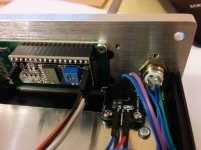
Attached are the close-ups of the LCD display mounting on my unit. The original tapped holes are not used (visible in the pictures). The height of the milled away area on my front panel is just enough to accommodate the LCD display itself plus maybe a couple of millimeters for loose fit. I use M3 size screws which need 2.5mm diameter pilot hole for the tap. On the bottom edge of the LCD display the holes are really close to the milled away area but there was still enough space to accommodate the M3 threaded holes. You just have to accurately drill two 2.5mm diameter pilot holes and the thread would still hold the screws even if it cuts a bit into the open edge.
Regards,
Oleg
Regards,
Oleg
Attachments
Last edited:
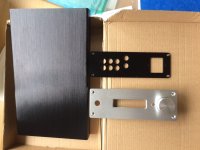
On mine the recess measures 25mm wide. I should probably buy the second chassis from the same vendor where I bought the first one and hope that I'll get the same 25mm wide recess. On the other hand, I plan to make myself a present and buy a 3D printer in the near future, and later the CNC router. Their prices are now down to around 300 Euro compared to 600Euro half a year ago, so both became more affordable. Then I'll be able to customize any chassis to my liking.
Regards,
Oleg
Regards,
Oleg
Hi Martti,
Yes, you can adjust the code to suit your encoder. I used an encoder with 64 pulses per revolution. Each pulse is 4 state changes thus allows theoretically up to 256 attenuation steps. I needed only 32 attenuation steps and wanted them to complete in one full turn of the encoder and thus I divided the total number of state changes by 8. In the last version of the firmware (see post #79) on lines 15 and 16 I introduced two variables EncoderResolution and MAXAttenuation which you can modify to suit your setup.
Regards,
Oleg
Thanks Oleg.
The encoder I have has only 20 pulses per revolution which means according to your instructions 4*20 = 80 state changes. But the attenuator has 32 steps, so I just set 4*32 = 128: "EncoderResolution = 128 - 1". This means that the encoder rotates more than one full circle, but I don't mind. Works just fine.
The encoder I have has only 20 pulses per revolution which means according to your instructions 4*20 = 80 state changes. But the attenuator has 32 steps, so I just set 4*32 = 128: "EncoderResolution = 128 - 1". This means that the encoder rotates more than one full circle, but I don't mind. Works just fine.
Great! In principle there are cheap 15 pulses/30 detents per revolution mechanical encoders similar to your. They also cost about the same. So if making 1.5 turns for full volume is inconvenient you can simply get a 15 pulses/30 detents version. Then you can configure the controller for 30 attenuation steps per revolution using 2 state changes per detent instead of 4. If you want to try it I'll be happy to help to modify the code accordingly if you'll get difficulties with it.
Regards,
Oleg
Regards,
Oleg
- Home
- Source & Line
- Analog Line Level
- R-2R attenuator PCB layout question