Thanks for the offer! Now I know whom to ask if I fail to write my own code") I think writing the code should be a part of fun, unless it becomes a pain at some moment I'll probably copy I2C expander / relay driver combo from your design if you don't mind... but on a separate board.
I think writing the code should be a part of fun, unless it becomes a pain at some moment I'll probably copy I2C expander / relay driver combo from your design if you don't mind... but on a separate board.
I think writing the code should be a part of fun, unless it becomes a pain at some moment I'll probably copy I2C expander / relay driver combo from your design if you don't mind... but on a separate board.I am now wondering what voltage relays to select for +5VDC supply? I assume there will be some voltage loss on the driver IC which is around 1 volt if I understand the datasheet right. Should I go with 4.5V relays or increase the supply voltage to meet 5V across the relay coils? The idea to run Arduino and the relays from the same supply would only work for 7V supply and above since Arduino comfortable supply range is 7~12 VDC and 20VDC being the maximum. This would require using 6V, 9V or even 12V relays depending on the actual supply voltage. Can't decide...
maxw, I just managed to recognize on one of the pictures in your thread that you used 5VDC relays without problems with the 5VDC supply. The Omron datasheet indicates the "must make" voltage as 80% of nominal (which is ~4VDC for 5VDC model). Do your relays work reliably or my estimate of the voltage drop across the driver IC is wrong? Or may be the relay can still work reliably at their edge?
Thanks a lot maxw! You are really helping me here... I have very limited practical experience with all these, so your help is really appreciated!
I'll check if 4.5V relays are available at Mouser or Digikey. I'll probably take them instead of 5V parts just "in case" The idea to use a 5V supply is very attractive. Did you power the Arduino from the same 5V power supply?
I'll check if 4.5V relays are available at Mouser or Digikey. I'll probably take them instead of 5V parts just "in case"
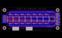
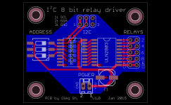
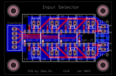
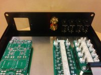
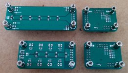
The idea to use a 5V supply is very attractive. Did you power the Arduino from the same 5V power supply?I have finally finished the attenuator board. I decided to move in/outs to one side as it has been suggested earlier in the thread. I also made the I2C relay driver board and the input selector board (see attached).
I'll send them for fabrication in the next days. If in the end everything will work I'll post gerber files here.
By the way, mouser has 4.5 VDC relays and the price is OK.
Oleg
I'll send them for fabrication in the next days. If in the end everything will work I'll post gerber files here.
By the way, mouser has 4.5 VDC relays and the price is OK.
Oleg
Attachments
Hey, that's great. If you were to interface it with a bleduino (BLEduino: Bluetooth 4.0 Made Easy) you can pair it with an bluetooth android app like this one.
https://play.google.com/store/apps/details?id=jgaudioremote.JGinfo
oh, you'd need to write a arduino sketch to turn the relays on / off.
https://play.google.com/store/apps/details?id=jgaudioremote.JGinfo
oh, you'd need to write a arduino sketch to turn the relays on / off.
I did not follow this thread, but I noticed that there is a ULN2803 relay driver with built-in diodes. The relay coil wires are going through the centre of the board. Great! you just created a hole bunch of antennae next to your audio lines. The higher the resistance of the R2R the better to pick up the noise. Allow for diodes across the relay coils at each relay or use relays with built-in diodes. E
Great! you just created a hole bunch of antennae next to your audio lines.
Isn't this a bit exaggerated ? Wiring is short and it is the coils that would receive RF, if at all.
Hi Jean-Paul,
This thread has been a sleep for more than a year. In this time I completed all the boards mentioned here and even installed the diodes suggested by mickeymoose. If I understood it correctly, he meant the back EMI of the switching relays to be the noise source. In the end I have no pops or other audible problems when adjusting the volume but since I did not try it without the diodes I can not tell if they helped here.
Regards,
Oleg
Progress report
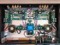
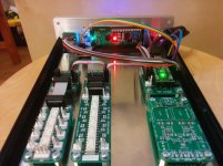
The top view of what is assembled and working is shown in the attachment. The idea is to have a four channel volume control for the left, right, center and subwoofer channels for music and home cinema duties. All channels are electrically isolated, quad mono so to say. The inputs are configured such that if stereo input is selected the controller would allow balance control (left predrilled empty space on the front panel is for the balance control knob and indicator), and will disable the balance control once the four channel inputs are selected. The project is still in progress and needs more work to complete but I already listen to the music using it. I use Subbu DAC V3 as the source. The volume controller/input selector feeds dual mono MyRef FE power amp which drives a pair of Zaph ZDT3.5 speakers. I also have half finished ZD3C center speaker but due to the lack of space for it I have no drive to complete it.
Regards,
Oleg
Attachments
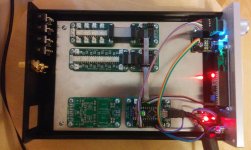
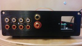
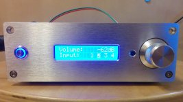
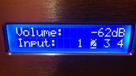
After a long time I finally started to put together a new version of the attenuator. Attached pictures show current state of the project. The arduino code is almost done including the remote control part. It needs a bit of optimization and clean up, but otherwise is fully functional already. What's left is to finish wiring and add output buffer. I've made provision for my OPA1622 based headamp but haven't made a final decision on it yet. The LCD display in the pictures looks a bit overexposed but in reality it looks like shown on a separate "screen only" image.
The attenuator operates without clicks and pops in the speakers during attenuation. It uses only 6 relays, one of which is used for mute. Thus it has 32 (2dB) steps for 62dB attenuation range which I find more than sufficient after playing with my previous attenuator version.
Regards,
Oleg
The attenuator operates without clicks and pops in the speakers during attenuation. It uses only 6 relays, one of which is used for mute. Thus it has 32 (2dB) steps for 62dB attenuation range which I find more than sufficient after playing with my previous attenuator version.
Regards,
Oleg
Attachments
-
 R-2R.Attenuator.Assembled.Rear.Inside.jpg649.3 KB · Views: 299
 -
 R-2R.Attenuator.Assembled.Front.Inside.jpg632.1 KB · Views: 493
 -
 R-2R.Attenuator.Assembled.Layout.jpg631.2 KB · Views: 481
 -
 R-2R.Attenuator.Assembled.Back.jpg717.9 KB · Views: 484
 -
 R-2R.Attenuator.Assembled.Front.jpg729.7 KB · Views: 531
 -
 R-2R.Attenuator.Assembled.Display.jpg960.6 KB · Views: 258
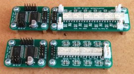
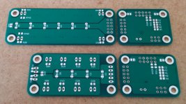
Attached are schematics and PCBs closeups for completeness. I'll post the arduino code later, when it is finalized.
Regards,
Oleg
Regards,
Oleg
Attachments
-
 R-2R.Attenuator.New.Assembled.Top.jpg236.6 KB · Views: 288
 -
 PCBs.Bottom.jpg192.9 KB · Views: 264
 -
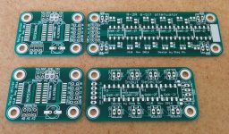 PCBs.Top.jpg289.2 KB · Views: 308
 -
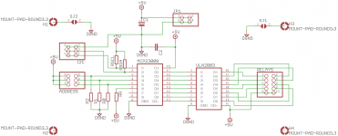 RelayDriver.Schematic.png23.5 KB · Views: 290
 -
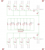 InputSelector.Schematic.png20.6 KB · Views: 320
 -
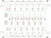 R-2R.Attenuator.Schematic.png24 KB · Views: 344
 -
 R-2R.Attenuator.New.Assembled.Bottom.jpg191.5 KB · Views: 322
- Home
- Source & Line
- Analog Line Level
- R-2R attenuator PCB layout question