Hello!
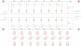
I've been playing around with R-2R attenuator board for my diy system. The attenuator will be controlled by the Arduino. The attached schematic is fairly standard. I have sketched two possibilities: with through hole and SMD resistors. I have not decided yet which way to go but am more inclined towards SMD version. I also decided to wire the relay coils off board via the pinheads. I've tried to follow the signal while routing the PCB but may have overlooked something. I am new to the PCB design.
Could some of the gurus advise me if either side of the PCB (through hole or SMD) have problems? Any input is highly appreciated!
OlegSh
Attachments
I'll try to be more specific about my worries.
Could the connection scheme of the relay coils induce "switching" noise into the audio signal when relays turn on/off? There will be an unavoidable loop created by the wires feeding the relay coils. Four layer PCB would be easier but it is too expensive.
Could the connection scheme of the relay coils induce "switching" noise into the audio signal when relays turn on/off? There will be an unavoidable loop created by the wires feeding the relay coils. Four layer PCB would be easier but it is too expensive.
You need to add back-EMF snubber diodes across the relay coils, as close as possible to the coil (surface mount on the bottom?). I also would try to bring out all connections to one side of the board (one common for the relays?). This way you could flip the board for troubleshooting. E
I know jackinnj.
But my interest is to learn something by doing. Being new to the PCB routing I would like to keep my PCB simple and may be avoid problems which others might have by making their designs to suit different uses or parts selection. I'll post the board here if I succeed to create anything decent") Otherwise I'll end up buying one of the existing boards but will definitely have some knowledge after this try...
Otherwise I'll end up buying one of the existing boards but will definitely have some knowledge after this try...
Also there are not so many designs using SMD resistors which allow to keep the layout really compact.
But my interest is to learn something by doing. Being new to the PCB routing I would like to keep my PCB simple and may be avoid problems which others might have by making their designs to suit different uses or parts selection. I'll post the board here if I succeed to create anything decent
Otherwise I'll end up buying one of the existing boards but will definitely have some knowledge after this try... Also there are not so many designs using SMD resistors which allow to keep the layout really compact.
If you use a relay driver IC like ULN2003A there is no need for the diodes.I just checked and SMD version of 1N400x would fit perfectly between the relay pins on the underside of the PCB.
Some info including eagle files from one I made a couple years ago here:
http://www.diyaudio.com/forums/anal...i2c-relay-selector-attenuator-tube-stage.html
I would go SMD and keep all the resistors on one side of the PCB
Hi maxw,
I've seen your board before. I aim at a similar layout except I would prefer to have controller separated from the audio circuit. This would allow to use any possible solution for controlling the relays.
I also have a question why placing the resistors on the same side is beneficial? In my layout I made it such that the signal and its return matching exactly by placing the parallel resistors on the ground plane side.
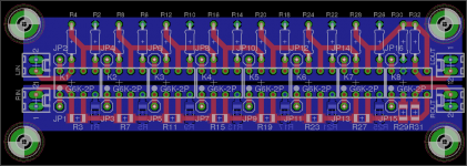
Below is the current state of the PCB. I'm in doubt if the relay coils wiring isn't too tight? I checked the creepage distance between traces for 5 VDC and it seems to be sufficient. Now I'm wondering if PCB producer can handle such a spacing...
Now regarding the termination resistor. The attenuator supposed to see a fixed load which is a combination of input resistance of the following stage and the resistor to ground on the board (if necessary) to match the desired value. Would it have any drawback if I use a DIP switch and install a set of different resistors to ground? This way I could adjust the load seen by the attenuator by simply operating the switch... Are there any sonic concerns of such an approach?
Regards,
OlegSh
I've seen your board before. I aim at a similar layout except I would prefer to have controller separated from the audio circuit. This would allow to use any possible solution for controlling the relays.
I also have a question why placing the resistors on the same side is beneficial? In my layout I made it such that the signal and its return matching exactly by placing the parallel resistors on the ground plane side.
Below is the current state of the PCB. I'm in doubt if the relay coils wiring isn't too tight? I checked the creepage distance between traces for 5 VDC and it seems to be sufficient. Now I'm wondering if PCB producer can handle such a spacing...
Now regarding the termination resistor. The attenuator supposed to see a fixed load which is a combination of input resistance of the following stage and the resistor to ground on the board (if necessary) to match the desired value. Would it have any drawback if I use a DIP switch and install a set of different resistors to ground? This way I could adjust the load seen by the attenuator by simply operating the switch... Are there any sonic concerns of such an approach?
Regards,
OlegSh
Attachments
Sounds good!I've seen your board before. I aim at a similar layout except I would prefer to have controller separated from the audio circuit. This would allow to use any possible solution for controlling the relays.
I honestly don't know. I just did it this way in order to use less vias and because I'd seen this type of separation in other designs. I don't really know what I'm doingI also have a question why placing the resistors on the same side is beneficial?
PCB manufactures will state their tolerances and sometimes even let you load them into Eagle with the DRC file and then Eagle will tell you if it's too close in the DRC check. OSHPark do this.Below is the current state of the PCB. I'm in doubt if the relay coils wiring isn't too tight? I checked the creepage distance between traces for 5 VDC and it seems to be sufficient. Now I'm wondering if PCB producer can handle such a spacing...
Just discovered that Mouser does not stock 1206 SMD Susumu resistors which I had in mind while making the PCB layout. May be someone could recommend other good quality not too expensive thin film resistors in 1206 size?
I can change the pads for 0805 and be done with it but I would prefer the 1206 parts if possible since they are slightly easier to solder.
I can change the pads for 0805 and be done with it but I would prefer the 1206 parts if possible since they are slightly easier to solder.
Panasonic usually have a good range. Just go to the category and search for thin-film and 1206 and see what's available. It can be difficult to get all the values in one range. I think I also ordered from RS components once or twice as well as Mouser and Farnell. Shop by availability, price, specs and don't believe the "X brand sounds great" type of opinions
Thanks for the hint maxw!
Just checked at Mouser and RS components and only few different values of thin film 1206 0.5~1% resistors are available while in 0805 way more values are there... This time I looked at several manufacturers at once. It also seems that thin film resistors are not so popular as most of stock is thick film and other types... Also what is the difference between metal film and other "film" types in terms of parameters relevant for audio? In principle I am not looking for something fancy here, just good quality not too noisy for audio purposes.
Just checked at Mouser and RS components and only few different values of thin film 1206 0.5~1% resistors are available while in 0805 way more values are there... This time I looked at several manufacturers at once. It also seems that thin film resistors are not so popular as most of stock is thick film and other types... Also what is the difference between metal film and other "film" types in terms of parameters relevant for audio? In principle I am not looking for something fancy here, just good quality not too noisy for audio purposes.
According to some DIYAUDIO correspondents, SMD resistors can be somewhat non-linear at audio frequencies. Thermal modulation. You might want to get some samples and check for this before committing to a PCB design. CMF55 through-hole devices would work without requiring a lot more real-estate.
Thanks for the suggestion. But my naive guess is that SMD parts if chosen right can be as good in terms of thermal stability as the through-hole ones since the materials available for both types should be similar.
Anyways, the PCB size is not a concern here. It's just the layout is much cleaner with SMDs and signal pass can be made very short and straight.
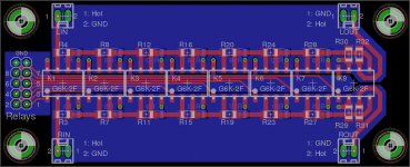
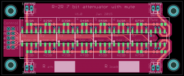
Below is the current PCB version. I finally changed the pads for 0805 resistors.
Now is the time for a small relay driver board to place between the arduino and the attenuator. As I understood the ULN2003A driver is 7 channels only. Will look for an 8 channel alternative.
Anyways, the PCB size is not a concern here. It's just the layout is much cleaner with SMDs and signal pass can be made very short and straight.
Below is the current PCB version. I finally changed the pads for 0805 resistors.
Now is the time for a small relay driver board to place between the arduino and the attenuator. As I understood the ULN2003A driver is 7 channels only. Will look for an 8 channel alternative.
Attachments
- Home
- Source & Line
- Analog Line Level
- R-2R attenuator PCB layout question