Hi all.
I added two electrolytic caps parallel to Dual PSU lines as close to hpf section to minimize aerial loops.
I chose 47uF - xo uses these,
The hum is gone to an extent as long as signal return is connected to an xo jack (otherwise it remains).
therefore I'm going to internally lump signal returns of xo and hpf to prevent the loud pops which occur when live replugging of jacks... (hopefully ok).
Another problem remains however...
Pink noise sound and no through put.
Perhaps this is RF now because I do not currently have ceramics onboard, I thought adding electrolytic would be enough.
shredhead, I think so - on the XO PCB there are 5x 'ceramic bypass' caps situated near each op-amp...
So you suggest 2x 100nF near the hpf op amp... but how? in series on the V+ line?
This reaffirms my doubt about how hpf op-amp power lines connect relative to dual power supply lines.
As I say I currently have 47uF in parallel on the HPF board but I don't know what comes after that...
It's Either:
A: PSU+ connects to V+ and PSU- to V- respectively, PSU common terminates here,
OR
B: PSU+ connects to V+ and PSU common to V- respectively, PSU- terminates here.
Any clues?
andrew, regarding xo points of LW xo - as far as I am aware there is only one f at each xo point...

I added two electrolytic caps parallel to Dual PSU lines as close to hpf section to minimize aerial loops.
I chose 47uF - xo uses these,
The hum is gone to an extent as long as signal return is connected to an xo jack (otherwise it remains).
therefore I'm going to internally lump signal returns of xo and hpf to prevent the loud pops which occur when live replugging of jacks... (hopefully ok).
Another problem remains however...
Pink noise sound and no through put.
Perhaps this is RF now because I do not currently have ceramics onboard, I thought adding electrolytic would be enough.
From what I understand it is important for the 100nF and 330nF ceramics to be as close to the chip's pins as possible.
shredhead, I think so - on the XO PCB there are 5x 'ceramic bypass' caps situated near each op-amp...
So you suggest 2x 100nF near the hpf op amp... but how? in series on the V+ line?
This reaffirms my doubt about how hpf op-amp power lines connect relative to dual power supply lines.
As I say I currently have 47uF in parallel on the HPF board but I don't know what comes after that...
It's Either:
A: PSU+ connects to V+ and PSU- to V- respectively, PSU common terminates here,
OR
B: PSU+ connects to V+ and PSU common to V- respectively, PSU- terminates here.
Any clues?
andrew, regarding xo points of LW xo - as far as I am aware there is only one f at each xo point...
Last edited:
A mono 2way crossover has two filters.
A high pass feeding the treble to the treble driver and a low pass feeding the bass/mid to the bass/mid driver.
For most active crossovers these two filters have the same frequency.
A mono 3way has four filters
A high pass for the treble driver.
A low pass for the bass driver.
A high pass followed by a low pass for the mid driver.
This usually requires two very different frequencies for the four filters.
Your diagram does not show this.
What you quoted me about:
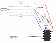
I was talking about the power supply. You can see the caps I was referring to in this picture. They are the closest caps to the voltage regulator chips.
This picture might help you. I put the 100nF ceramic bypass cap between the V+ and V- because I read that this prevents that cap from injecting noise into the ground. I really do it because it is way easier than using two, one on each power in pin and I'm lazy. Are you using the same PSU for all of these filters?
Keeping the PSU grounds away from the chip's signal grounds really helped my project get lower noise figures thanks to the advise of some bada$$ members around here.
I'm not sure that I understand what you mean about the pink noise and no thru put.
Attachments
Last edited:
Alright, thanks for getting back,
Yes xo and hpf are sharing same dual PSU lines.
~ Now because they are, when you illustrate V- and PSU GND being coupled (to provide - and + voltages for hpf circuit) - this translates (to me atleast) 'shorting dual psu lines'. Perhaps i'm missing something - I doubt the xo (which needs unshorted dual supply lines) can still function with this 'short' in place?
...though I'm sure this why you asked in first instance if I have one psu.
Regarding ceramic cap - You make clear that there should be 1 between V+ and V terminals of the op-amp. I'll give this a try, though again this translates 'shorting V+ and V-' (considering this cap is not a polarized component) also... care to enlighten?
Regarding grey 'signal ground on PCB' connection - There isn't a common node available on either PCB/vero, but I'm sure lumping all commons and signal returns is an equivalent method.
Many thanks for your help.
I could just scrap HPF and be on my way but I plan on getting a turntable (in hope for some analog sound as digital just isn't the same).
Pink noise is what I'm currently experiencing through the circuit and when I apply say a 30hz tone through the circuit, it proves inaudible and pink noise remains. It resembles radio frequency static... which is what I think the ceramic could be for.
Last edited:
Hey Giro, you should know that I'm not at the level where I'm giving classes on this stuff. I'm just showing you what has worked for me in the past. I understand where you would think that it shorts the 2 rails but it doesn't, look at the power supply. It does the same thing and uses different value caps in several places to store power for the different demands.
I have NO idea what would give you the radio static type noise. That's never happened to me before. I have had an accident where a signal pin had a tiny fragment of solder bridge it to a power rail and take out an op amp. It was noisey but like super wild oscillations at random, didn't sound anything like RF stuff.
Keep on truckin' G, you'll get it. Maybe try connecting the power supply to only the xover or just the HPF and see if you get signal. Or if you get stumped enough, hook the PSU to a simple buffer circuit on a breadboard to see if you can get a clean signal so you can have some faith in your power supply. Then you can move on to ruling out other things.
Alright no probs i understand...
Some quick feedback - I connected the bypass ceramic across +- terminals.
As I say the hum is eliminated now but this air like noise remains...
I've uploaded the air sound the hpf circuit is outputting to soundcloud:
https://soundcloud.com/short_swiss/noise
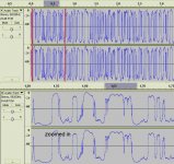
I've attatched screenshot of waveform to this post also.
Any suggestions what this could be would be of great help...
Thanks
Some quick feedback - I connected the bypass ceramic across +- terminals.
As I say the hum is eliminated now but this air like noise remains...
I've uploaded the air sound the hpf circuit is outputting to soundcloud:
https://soundcloud.com/short_swiss/noise
I've attatched screenshot of waveform to this post also.
Any suggestions what this could be would be of great help...
Thanks
Attachments
Last edited:
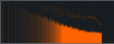
I don't know what this noise is coming from but it gets worse the lower in frequency you go so I don't think this is a problem with the grounding scheme.
I would re-check whatever circuit this is because something is majorly wrong. Like I said before, troubleshoot your stuff by simplifying it until it starts working. What output is giving you this noise? Are all filters hooked up for this noise? Try just getting one filter to work right. Try connecting a simple voltage follower buffer circuit to your power supply to rule out problems with it. My guess is something is bridged that shouldn't be or something got left out that should be connected to your circuit.
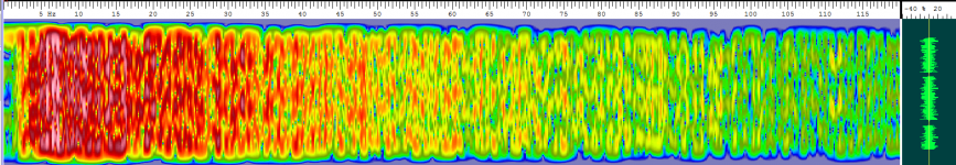
Anyway, here are some visuals of the noise for any other members that might recognize the problem.
I would re-check whatever circuit this is because something is majorly wrong. Like I said before, troubleshoot your stuff by simplifying it until it starts working. What output is giving you this noise? Are all filters hooked up for this noise? Try just getting one filter to work right. Try connecting a simple voltage follower buffer circuit to your power supply to rule out problems with it. My guess is something is bridged that shouldn't be or something got left out that should be connected to your circuit.
Anyway, here are some visuals of the noise for any other members that might recognize the problem.
Attachments
You need to use a better low noise psu, at least with LM317/337
You think the PSU is to blame for this noise? I thought L7815/L7915 combos usually have better noise numbers than the LM317/337 in the datasheets?
thanks all for your response, I must say though that the crossover works fine on the same power supply and it uses exactly the same op amp (BB2134).
As I say when I play a straight sinusodial through just the hpf, i can't hear anything but this rumble.
The crossover works beautifully with hpf omitted from path.
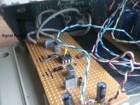
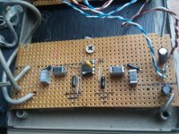
I've attached pics of hpf circuit.
I wonder if maybe resistor on the output line is essential... I don't have any spare to try this out.
I find it fascinating that the sound largely resembles turntable rumble! not the desired effect.
Thanks again.
As I say when I play a straight sinusodial through just the hpf, i can't hear anything but this rumble.
The crossover works beautifully with hpf omitted from path.
I've attached pics of hpf circuit.
I wonder if maybe resistor on the output line is essential... I don't have any spare to try this out.
I find it fascinating that the sound largely resembles turntable rumble! not the desired effect.
Thanks again.
Attachments
Last edited:
- Status
- This old topic is closed. If you want to reopen this topic, contact a moderator using the "Report Post" button.
- Home
- Source & Line
- Analog Line Level
- Hum issue in hpf circuit