.
I think you might be looking for something like these:
Simple Mixer Schematics (scroll to the bottom)
Advanced Mixer circuits
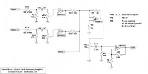
I'm also posting a schematic of my own below. This is an explanatory schematic, not a construction project. It's intended to lay things out a little more understandably.
On the left are the individual inputs. "MORE" means you can have as many as you want, but no more than a dozen or so is probably wise.
The mixer, U2, puts out a mixed but inverted signal. This is the nature of the beast, virtual earth mixers invert the signal.
Following U2, the next stage, U3, would usually be, for instance, a tone control, which also inverts the signal, so things come out right. In this particular case U3 does not invert, but then this is an example, not a project.
Hope this might be of some help.
.
I think you might be looking for something like these:
Simple Mixer Schematics (scroll to the bottom)
Advanced Mixer circuits
I'm also posting a schematic of my own below. This is an explanatory schematic, not a construction project. It's intended to lay things out a little more understandably.
On the left are the individual inputs. "MORE" means you can have as many as you want, but no more than a dozen or so is probably wise.
The mixer, U2, puts out a mixed but inverted signal. This is the nature of the beast, virtual earth mixers invert the signal.
Following U2, the next stage, U3, would usually be, for instance, a tone control, which also inverts the signal, so things come out right. In this particular case U3 does not invert, but then this is an example, not a project.
Hope this might be of some help.
.
Attachments
Last edited:
.
<< my idea was to just get two really nice phono amps...and then hook them up to a summing amp >>
Or easiest of all, you might just be interested in the Behringer XENYX 502 mixer. It goes for something like $45 at Amazon, zzsounds, here & there.
CAUTION: Most mixers are "line-level" units, meaning they expect an input of [very] approximately 1 volt. The expected hookup is line-out ~> line-in. Any preamp can be expected to have a line-out connector, but check this.
Headphone-out connectors can usually serve for line-out, but check this too.
.
Hey thanks for the input!
Yeah I've been familiar with that page. Very nice explanation (specially for a complete electronics idiot like myself). I'm definitely going for something along the lines of the "simple virtual earth active mixer with input attenuation". Just trying to understand how I can choose the right opamp for that architecture. I feel like to a certain extent, any opamp (with same number of inputs) would work, the only difference would be the power supply voltage (?)
(Sorry for what I'd image are completely stupid questions to you guys)
Sure, I could just buy a ready made mixer. But I'm not interested in that. Also, the general online nuance on comercial mixers is that they're not that great in terms of sound, and it would be relatively easy to top them off with very little cost involved.
Thanks again
Hey guys,
So I think I'm going with a very basic virtual ground opamp summing amplifier setup. I have a bunch of NE5543's laying around. I thought I'd start experimenting with those...I figure I could do it with two inverting stages, does anyone have any recommendations regarding power supply for these?
If you're careful, you should be able to better a lot of commercial mixers. Linear Technology has some nice 3 pin regulator versions. Watch out for too many summing inputs to a single op amp, though. Each additional one will increase the noise gain and thus decrease the bandwidth.
Last edited:
.
<< trying to understand how I can choose the right opamp for that architecture >>
For myself it would be a no-brainer. The NE5532 is available for 50 cents each on eBay. For many, many years it was top of the line, only recently improved upon--and some question those "improvements."
Big secondary advantage is the cost. Not to say you'll burn up a few, but, ahem, things do happen.
.
Hmmm...thank you, and please don't hesitate about elaborating any further on what you mean with "If you're careful"
Most of the power supplies I see just consist of a few capacitors, are you suggesting only using a voltage regulator instead? would that be a better option? what would the implications be...?
And yeah, I'm not looking to have more than 3 channels...should be fine right?
Thanks again
Most of the power supplies I see just consist of a few capacitors, are you suggesting only using a voltage regulator instead? would that be a better option? what would the implications be...?
And yeah, I'm not looking to have more than 3 channels...should be fine right?
Thanks again
bentsnake, Please excuse my ignorance but I'm trying to understand why you have an opamp before the summing stage in your sketch. What is that doing for the signal?
Also, what would be the difference between having the level control between the two last opamps (as in your design) vs after the last opamp?
Also, what would be the difference between having the level control between the two last opamps (as in your design) vs after the last opamp?
Hmmm...thank you, and please don't hesitate about elaborating any further on what you mean with "If you're careful"
Most of the power supplies I see just consist of a few capacitors, are you suggesting only using a voltage regulator instead? would that be a better option? what would the implications be...?And yeah, I'm not looking to have more than 3 channels...should be fine right?
Take a look at a good commercial unit to get some ideas to start with. Lay out the pcbs compactly with connectors close by or board mount. Use good op amps designed for audio with low noise. Use dedicated, regulated power bipolar voltage supplies, well filtered before the regulator inputs, with heavy local decoupling at the op amp pins. Level controls can be a weak point, choose these with care. Consider peak signal levels to determine the gain structure, the number of stages, where to put the level controls in the circuit.
Last edited:
.
<< bentsnake, Please excuse my ignorance but I'm trying to understand why you have an opamp before the summing stage in your sketch. What is that doing for the signal? ...Also, what would be the difference between having the level control between the two last opamps (as in your design) vs after the last opamp? >>
Stop! That circuit was supposed to be illustrative only. I wanted to show you the distinction between the several input stages (U1a...b...c...), the single mixing stage (U2), and the single following stage (U3)--the single following stage might be amplification, tone controls, whatever. You're not supposed to study it, you're supposed to say, "Oh, so like...3 different sections...yeah," and forget about it.
Op amp U1a...b...c... is a "buffer." Buffers have unity gain, very high input impedance, and very low output impedance. Their reason for existence is to give absolute separation between the input signal and any circuitry that follows, which is just want you want.
Ignore the level (volume) control, it's wrong. So was I wrong to post such an incomplete circuit, but it seemed like a good idea at the time, and of course now I can't take it down. Ignore the whole thing.
.
.
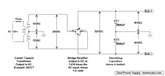
<< does anyone have any recommendations regarding power supply for these?...Most of the power supplies I see just consist of a few capacitors, are you suggesting only using a voltage regulator instead? would that be a better option? what would the implications be...? >>
In partial atonement for my former sins, and to prove I'm a glutton for punishment, a schematic. This one too is only illustrative, it's intended to give you the general idea. But this one has the big advantage of being correct, you could bolt it together right here, right now, and it would work as intended.
Building this unit would cost something like $25 in parts, including the transformer. As with "which is the best op amp," others have different ideas about how these things should be done.
.
Attachments
.
<< does anyone have any recommendations regarding power supply for these?...Most of the power supplies I see just consist of a few capacitors, are you suggesting only using a voltage regulator instead? would that be a better option? what would the implications be...? >>
In partial atonement for my former sins, and to prove I'm a glutton for punishment, a schematic. This one too is only illustrative, it's intended to give you the general idea. But this one has the big advantage of being correct, you could bolt it together right here, right now, and it would work as intended.
Building this unit would cost something like $25 in parts, including the transformer. As with "which is the best op amp," others have different ideas about how these things should be done.
.
Yes, and to add regulators after the caps, just use a 35VCT or so transformer to allow for the regulator drops. It would be best to add another RC filter before the regulator first though, to make it easier on the regulators to reject the ripple.
Last edited:
")
.
<< does anyone have any recommendations regarding power supply for these?...Most of the power supplies I see just consist of a few capacitors, are you suggesting only using a voltage regulator instead? would that be a better option? what would the implications be...? >>
In partial atonement for my former sins, and to prove I'm a glutton for punishment, a schematic. This one too is only illustrative, it's intended to give you the general idea. But this one has the big advantage of being correct, you could bolt it together right here, right now, and it would work as intended.
Building this unit would cost something like $25 in parts, including the transformer. As with "which is the best op amp," others have different ideas about how these things should be done.
.
Yes, and to add regulators after the caps, just use a 35VCT or so transformer to allow for the regulator drops. It would be best to add another RC filter before the regulator first though, to make it easier on the regulators to reject the ripple.
just wanted to let you guys know that this post has helped me, thank you.
Interesting topic..
I always wondered how will sound Djing with two high quality preamplifiers with tube phono stage, with a simple 2 channels passive rotary mixer like this:
Passive Rotary DJ Mixer | Music mixer, Dj, Music mixing
unfortunately the guy that designed the mixer and had the website Nymeria is not active on the web anymore...
Last edited:
Hi all and @BCmoore,
Did you move forward with your simple mixer project?
I am looking at this too and would be interested in your feedback.
By the way, the most interesting article I have found is: High Quality Sound Mixer
Thanks
Did you move forward with your simple mixer project?
I am looking at this too and would be interested in your feedback.
By the way, the most interesting article I have found is: High Quality Sound Mixer
Thanks
I just started working into one, gathering info and looking at the same diagrams as shown. Testing block circuits.
I have been looking at the Bruno Puetzeu volume control, a little complicated but would make a great addition, there are some implementation of it available at low cost to prototype. It has a very nice power supply section. Also, the very simple volume control from hypnotoad , on addition to the ones you are referring.
Also some good info on the esp article about dj isolators, that is basically a mix of three filters
- Home
- Source & Line
- Analog Line Level
- very very simple DJ mixer aka summing amp?