Hello DIYers
First of all I know these things have been on here quite a few times and I have read most of the threads about it but I still have few questions.
Ok so here it goes
First of all I am trying to do something like this:

Will there be a big problem if I put all this in same case?
Ok so there will be ODAC or something similar + two external stereo inputs one RCA and one 1/4" jack.
Everything will be fed into inverting input on opamp (don't know whitch one yet) and after the first one it will go to second one to correct phase. Is second one even needed?
After this stage I don't know exactly how to continue. How to connect both speaker and headphone amp? can both be driven from opamp output or should there be something in between?
I want to use one potentiometer for volume for both amps where should I put it on input or output of opamp?
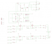
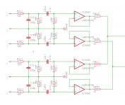
Here is schematic I have so far. Only one channel shown

Thanks
First of all I know these things have been on here quite a few times and I have read most of the threads about it but I still have few questions.
Ok so here it goes
First of all I am trying to do something like this:
Will there be a big problem if I put all this in same case?
Ok so there will be ODAC or something similar + two external stereo inputs one RCA and one 1/4" jack.
Everything will be fed into inverting input on opamp (don't know whitch one yet) and after the first one it will go to second one to correct phase. Is second one even needed?
After this stage I don't know exactly how to continue. How to connect both speaker and headphone amp? can both be driven from opamp output or should there be something in between?
I want to use one potentiometer for volume for both amps where should I put it on input or output of opamp?
Here is schematic I have so far. Only one channel shown
Thanks
Hello
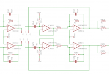
So I played around a bit and I got something like this.
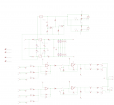
New schematic

And this would correspond to gain changes like this

But now I could play a bit more with resistors to get better curve. Should I use lower value pot and lower value resistors or is this good enough.
So I played around a bit and I got something like this.
New schematic
And this would correspond to gain changes like this
But now I could play a bit more with resistors to get better curve. Should I use lower value pot and lower value resistors or is this good enough.
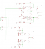
Ok after some simulation that is probably wrong I got some results
Schematic in spice (resistor numbering not the same)

and result is

I'll try without R5 across pot.
Is this changing volume with gain same thing as attenuating at input? What is better?
Now about PS for this would it be better to have regulators on same board or on separate?
Schematic in spice (resistor numbering not the same)
and result is
I'll try without R5 across pot.
Is this changing volume with gain same thing as attenuating at input? What is better?
Now about PS for this would it be better to have regulators on same board or on separate?
Hello,
The circuit looks already good. Use 10u for C1,C2,C3 (better availability and similar price). C5 is to low. Your need at least 10u if the input impedance of the next step is taken into account.
It is also possible to use an attenuator at the input. Small advantage of your current circuit is, that no current flows through the middle pin of the potentiometer.
It is not essential that the power supply regulator (LM317 or similar) is on the same board. If it is on the same board, the output impedance of the regulator is somewhat smaller (no cable).
It is important to have decoupling capacitors near the opv.
Good luck,
Udo
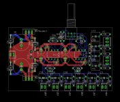
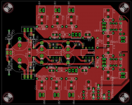
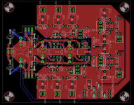
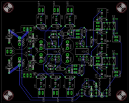
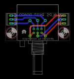
Ok bit of an update where I am so far. Layout is probably pretty bad.
Potentiometer will be mounted on front plate of the case so I just left sockets for it there.
I also tried to implement some sort of relays for turning outputs on and off.
Any comments.
Potentiometer will be mounted on front plate of the case so I just left sockets for it there.
I also tried to implement some sort of relays for turning outputs on and off.
Any comments.
Attachments
Originally Posted by udok
The power suply looks wrong. Why not use a bridge rectifier?
It looks as if he is using a transformer with only one secondary winding ? If so it's ok, if not i would use both windings & use a bridge
")
I don't know the 1N5818's are there either ?
Small board for potentiometer RK27/RK097 for now.
Or I could go with one of those stepped attenuators from ebay such as
DACT Type 21 Stepped Attenuator Potentiometer 10K
Valab 23 Step Attenuator Potentiometer 10K Stereo Log
Valab 23 Step Ladder Type Attenuator Potentiometer 10K Log Stereo
Or I could go with one of those stepped attenuators from ebay such as
DACT Type 21 Stepped Attenuator Potentiometer 10K
Valab 23 Step Attenuator Potentiometer 10K Stereo Log
Valab 23 Step Ladder Type Attenuator Potentiometer 10K Log Stereo
Attachments
The Diodes after the regulator are unnecessary.
You can find some basics here: HTTP 301 This page has been moved
A online calculator is here (in German): Spannungsversorgung und Netzteile
You can find some basics here: HTTP 301 This page has been moved
A online calculator is here (in German): Spannungsversorgung und Netzteile
Hey
I kinda put this project aside for a while now. But no I hope I'll actually continue.
First of all thanks udok for those links I helped to read a bit more about regulators.
Ok so this past month I was still thinking about this circuit and decided on few changes to it.
First of all two inputs will be good enough One for DAC that will sit inside same enclosure and one for external gear. After talking with one of my co-workers he nudged me in SMD direction. So with this change I have enough space on same PCB for preamp and headphone section. Now I can make powersupply from two secondaries not with voltage doubler like I had before.
Found this link and maybe I should implement something similar in my design. Like add buffers on input and buffer inside gain control.
I'll draw new schematic today or tomorrow.
I kinda put this project aside for a while now. But no I hope I'll actually continue.
First of all thanks udok for those links I helped to read a bit more about regulators.
Ok so this past month I was still thinking about this circuit and decided on few changes to it.
First of all two inputs will be good enough One for DAC that will sit inside same enclosure and one for external gear. After talking with one of my co-workers he nudged me in SMD direction
. So with this change I have enough space on same PCB for preamp and headphone section. Now I can make powersupply from two secondaries not with voltage doubler like I had before.Found this link and maybe I should implement something similar in my design. Like add buffers on input and buffer inside gain control.
I'll draw new schematic today or tomorrow.
- Status
- This old topic is closed. If you want to reopen this topic, contact a moderator using the "Report Post" button.
- Home
- Source & Line
- Analog Line Level
- preamp/mixer combo