Hi,
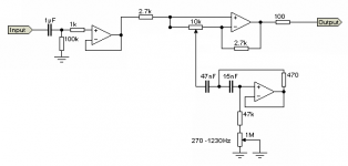
I have built an Active crossover based on Rod Elliots designs which works well. Recently, I have attempted to add a parametric equalizer that is based on this design Parametric and Sub-Woofer Equaliser, with the purpose of attenuating a few dBs of an unwanted peak in the response of the woofer.
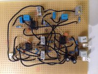
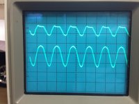
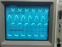
I have attached a few photos that illustrate what the oscilloscope says, along with the curcuit.
The circuit works (more or less) but it sounds like sh-t... The filter, which has both variable frequency and variable Q, can be adjusted as intended and if I lower the Q-value, the distortion is reduced. As far as I can tell, the attenuation of the sine wave is in the form of a cutoff of the top of the wave rather than a smooth attentuation of the whole wave, and by looking at the square wave, there seems to be heavy distortion.
The op-amps are Burr Brown OPA2134PA, the signal path caps are polypropylene.
I should tell you that I am a happy amateur, with very limited knowledge about what I am doing here, but what the heck, that shouldn't stop me right?
Is there an electronics wizard out there that could help me figure this one out?
I have built an Active crossover based on Rod Elliots designs which works well. Recently, I have attempted to add a parametric equalizer that is based on this design Parametric and Sub-Woofer Equaliser, with the purpose of attenuating a few dBs of an unwanted peak in the response of the woofer.
I have attached a few photos that illustrate what the oscilloscope says, along with the curcuit.
The circuit works (more or less) but it sounds like sh-t... The filter, which has both variable frequency and variable Q, can be adjusted as intended and if I lower the Q-value, the distortion is reduced. As far as I can tell, the attenuation of the sine wave is in the form of a cutoff of the top of the wave rather than a smooth attentuation of the whole wave, and by looking at the square wave, there seems to be heavy distortion.
The op-amps are Burr Brown OPA2134PA, the signal path caps are polypropylene.
I should tell you that I am a happy amateur, with very limited knowledge about what I am doing here, but what the heck, that shouldn't stop me right?
Is there an electronics wizard out there that could help me figure this one out?
Attachments
Last edited:
Is the resistor in the feedback path of the filter circuit really supposed to be that low, 470 ohms? And another thing is the layout of your circuit. Generally you should strive for a more compact layout that avoids long, looping connections that create stray circuit inductance. It appears that the power supply decoupling may be insufficient also. There should be some small value electrolytic caps in parallel with the disc caps, anything from at least 10uF on up to what ever physically fits is appropriate here.
Mike
Mike
Last edited:
Mike, check the link Parametric and Sub-Woofer Equaliser under "Simulated inductors". According to Rod Elliott, the feedback resistor should be 470 Ohms.
In terms of decoupling, i used this recommendtation from Elliot:
"Remember that all opamps need bypass capacitors on the supply pins, and I suggest that a 10uF electrolytic is used from both supply rails to earth for the whole board, and 100nF ceramic capacitors should be used as close as possible from each supply pin to earth."
My interpretation of this was to add 10uF electrolytics from the supply rails to earth and 100nF ceramics from the supply pins of each op-amp to earth. I am a bit uncertain though, should I add additional capacitors? Should the capacitors 10uF caps be 100uF?
The power supply is this: Power Supply for Preamps
In Rod's circuit he shows 4 filter sections with Four 10k pots in parallel.
The combination resistance of the 4 pots is 2.5k and yow show that you are using a single 10k pot.
This will change the gain of your boost and cut stage to extreme boost and cut!!
Try replacing the 2.7k resistors on both side of the pot to 10k and see if that helps.
Also if you are feeding a square wave into a filter circuit you will get such waveforms, but, it does look like the filter is ringing and trying to oscillate and this is caused by having too much gain as I mentioned above.
FWIW
jer")
The combination resistance of the 4 pots is 2.5k and yow show that you are using a single 10k pot.
This will change the gain of your boost and cut stage to extreme boost and cut!!
Try replacing the 2.7k resistors on both side of the pot to 10k and see if that helps.
Also if you are feeding a square wave into a filter circuit you will get such waveforms, but, it does look like the filter is ringing and trying to oscillate and this is caused by having too much gain as I mentioned above.
FWIW
jer
Last edited:
One step towards solving the problem
You were correct when it comes to the power supply sag. I had accidentally wired the powersupply incorrectly to the plug pack, which gave me +8V/-12V.
Also, I think gerald is correct with the gain. I have now replaced the 2.7k resistors for 10k resistors. I will drive off to my friend who has an oscilloscope tomorrow and post the results.
If I can just get the prototype working, I will have someone create a proper PCB for this, so the stray inductance problem associated with the long looping wires is eliminated.
- Status
- This old topic is closed. If you want to reopen this topic, contact a moderator using the "Report Post" button.
- Home
- Source & Line
- Analog Line Level
- Problem with parametric equalizer