Are you sure you do not reverse a transistor reference or a wrong reference?
Please explain...
YesHe probably means PNP instead NPN or vice versa.
Or two PNP instead NPN+PNP
etc...
Yes
Or two PNP instead NPN+PNP
etc...
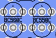
I have both PNP (BC560C) on the left, and both NPN (BC550C) on the right.
I cut off the heat shrink holding the transistors face to face, and separated them. I checked them closely with high magnification, and none of the 4 appear damaged or burnt???
Thanks for your input,
Lacro
Attachments
Good point.
Sorry I haven't been able to help so far, I have been preoccupied with fixing Frankenstein, my car. It's a victim of a bad engine swap. The wrong distributor is bolted on backwards, among other things. I just finished replacing the head gasket and the oil pan, and now I have to figure out how to get the crank pulley bolt off to change the timing belt.
Sorry I haven't been able to help so far, I have been preoccupied with fixing Frankenstein, my car. It's a victim of a bad engine swap. The wrong distributor is bolted on backwards, among other things. I just finished replacing the head gasket and the oil pan, and now I have to figure out how to get the crank pulley bolt off to change the timing belt.
I do not know the pcb that you use but it may have an engraved inductor and you forgot the link that is on the +10V.
I soldered the link for the inductor
Good point.
Sorry I haven't been able to help so far, I have been preoccupied with fixing Frankenstein, my car. It's a victim of a bad engine swap. The wrong distributor is bolted on backwards, among other things. I just finished replacing the head gasket and the oil pan, and now I have to figure out how to get the crank pulley bolt off to change the timing belt.
No problem Kean, I will eventually get this sorted out. I know what you mean about removing a crank pulley. I had to do that on a Honda Accord a long time ago, and it took a socket/breaker bar/ long pipe to loosen it. BTW/ some bolts are LH thread, and some are RH thread. I am sure you already know that.
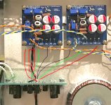
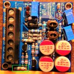
I have copied and cleaned-up a picture from an earlier post.
Examine the polarity of the four elcos on each board.
I have the caps installed with the correct polarity.
Now that I have the transistors off the board, is there a way I can check the output of the regulator if I power it, without damaging the Kuartlotron?
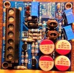
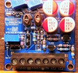
Photos of the board attached:
Attachments
It's a 92 honda civic LX, with the engine block swapped in from a 91. The cylinder head is from the 92. I just replaced the thermostat valve but it still runs too cool to turn on the radiator fan, and I know the radiator fan works all the way up the the thermoswitch which I just replaced as well.
Yes - I swapped this resister, and both regs with the ones on the second board which is a working board. The resistor measures 68R, and it with the regs installed on the good board are working, but the known good parts from the working board exhibit the same problems when installed on the non working board.

It's a 92 honda civic LX, with the engine block swapped in from a 91. The cylinder head is from the 92. I just replaced the thermostat valve but it still runs too cool to turn on the radiator fan, and I know the radiator fan works all the way up the the thermoswitch which I just replaced as well.
Man, I don't envy you if changing the timing belt on the Civic is similar to the Accord which I was quoted $1000 to do at dlr.. Luckily a friend helped me do it. It took a solid 8 hours, and used $200 in parts at wholesale prices. There were actually 2 belts, and 2 idlers on the accord. Also, found the water pump was leaking while in there. Not a fun day, but it ended well.
Can be just a problem on the PCB, a cut off track or a bridge between two tracks!
I have inspected the board thoroughly with a high magnification eye loupe, and did't find any cut traces, or solder bridges.
I don't know if you read the whole thread, but it is possible that I reversed power ground with V- on the initial start up. I am not sure I did that, but it's possible.
It is possible that vias haven't connected between both sides of the board due to manufacturer defect, but this should not be a problem if both sides of the board are soldered to the lead.
At this point I would measure the resistance of all the resistors on-board. It looks to me by your transistor voltages that the Kuartlotron section is fine, and that the problem is in the regulator section.
At this point I would measure the resistance of all the resistors on-board. It looks to me by your transistor voltages that the Kuartlotron section is fine, and that the problem is in the regulator section.
I will be for this and especially on the track between the center of the inductance of the circuit and on the trimmer R1.It is possible that vias haven't connected between both sides of the board due to manufacturer defect, but this should not be a problem if both sides of the board are soldered to the lead.
- Home
- Source & Line
- Analog Line Level
- The Kuartlotron - keantoken's simple error-correction superbuffer