I never worked out an inverting version that seemed useful.
OK, thanks for letting me know!
I just assembled 4 boards using Fairchild BJTs, all of them sound fine, but one has a DC offset of 7mV (the others are around 2.5mV). If I set the DC trim pot so that DC offset goes down, the voltage on the input goes away from 0V: what shall I do?
Searching through the thread I found your advice to swap the BJTs: after swapping both pairs the DC offset went down to 3.5mV 
I always have this circuit on back of my head as something i wanna try out again in the near future. The only thing that holds me back is the fact that a relay must be used for the turn on thump. In my experience a relay always affects the sound even if its not in the signal path (because the associated circuit is still attached to the psu). But what if instead of relay a very slow biasing cmx circuit is used, right after the regulators? Or maybe the thump issue has been worked around since i last tried this circuit 6 months ago?
hi can you tell me if i use bc560b/550b instead of the ( c) types what would be the negative effects if any ? thanks
I know this is late, but the main difference will be you may have more offset before trimming.
I always have this circuit on back of my head as something i wanna try out again in the near future. The only thing that holds me back is the fact that a relay must be used for the turn on thump. In my experience a relay always affects the sound even if its not in the signal path (because the associated circuit is still attached to the psu). But what if instead of relay a very slow biasing cmx circuit is used, right after the regulators? Or maybe the thump issue has been worked around since i last tried this circuit 6 months ago?
It's worth a try, but I haven't tried it. I haven't tried to reduce turn-on thump.
Ive tried out almost two dozen circuits for my modular preamp this past year and your buffer is still coming up top. I want to rework the pcb so that to220 transistors can be used at high bias with heatsinks. If i go with to126 transistors i can make the layout such way that a pair of them can be bolted to the heatsink together (facing the same way) for a very effective thermal coupling. I feel that bigger transistors are the way to go because more current has so much benefit even for the simple linestage duty.
A delay relay will have to go on the same board. (I blew an amp months back because of the thump!) And i also want to use ground plane for this board. Ive been in the habit of seperating signal and psu ground for most of my pcb drawings
Should i do the same for your buffer? And if so should c1 and c2 radiate into the signal ground or psu ground?
I went and fitted the kuartlotron to my modular preamp. The sound is marvelous and it works trouble free, thank you keantoken.
One thing tho- i paralleled a 10ohm with the inductor thinking that it would suppress any ringing that might be present and it does seem to help the treble response a little bit. If youre dubious could you perhaps sim it and verify for us that it is indeed a good tweak?
One thing tho- i paralleled a 10ohm with the inductor thinking that it would suppress any ringing that might be present and it does seem to help the treble response a little bit. If youre dubious could you perhaps sim it and verify for us that it is indeed a good tweak?
Attachments
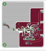
Interesting, that looks like an RF layout.
I did try the parallel resistor when I designed the Kuartlotron but it was unnecessary because the inductor is well damped by the emitter and resistor in series with it and the resonant frequency is too high to have much of an effect. If it did have an effect it would simply be that there is no error correction at it's resonant frequency in the RF range. However if the resistor is too low the inductor may fail to have it's important effect on overall stability. As a rule of thumb it should be much higher than the 56ohm resistor in series with the inductor, maybe 270-1k to damp the inductor without affecting the stability.
The Kuartlotron was somewhat stable without the inductor but there was some peaking that could amplify RF interference and might oscillate in certain conditions. So you might get away without it but I preferred the overall sound with it, and that is coming from someone who is easily driven crazy by either muted or overactive treble. The inductor was the most benign method of compensation I found and doesn't affect measured performance in the audio range.
The reason why it looks rf is prob because ive been taking notes from high speed rule book and applying it to my design. And if listening is any indicator the results speak for itself. The preamp is cleaner and quieter than most high end designs its come across. and with your buffer in place i doubt anything will be able to dethrone it for a while
Anyways, I thought the rule of thumb was to keep the damper resistor greater than 20times the coil resistance at which point even 22ohm is sufficient?
I will raise it even higher and report back.
As for the RF situation the inductor could be spraying radiation at that frequency which might have an unknown effect to the final sound. It seems more likely with an aircore and with the way i positioned it in my circuit. And if thats true the low ohm damper i added simply 'turns off' the inductor and its hf anomaly.
I plan on trying shielded inductor for this reason
Also, i proposed an idea earlier of a high current version of this circuit with bd139 140 at high v high bias. Im wondering if you think that idea is feasible. Thanks and regards
and with your buffer in place i doubt anything will be able to dethrone it for a while Anyways, I thought the rule of thumb was to keep the damper resistor greater than 20times the coil resistance at which point even 22ohm is sufficient?
I will raise it even higher and report back.
As for the RF situation the inductor could be spraying radiation at that frequency which might have an unknown effect to the final sound. It seems more likely with an aircore and with the way i positioned it in my circuit. And if thats true the low ohm damper i added simply 'turns off' the inductor and its hf anomaly.
I plan on trying shielded inductor for this reason
Also, i proposed an idea earlier of a high current version of this circuit with bd139 140 at high v high bias. Im wondering if you think that idea is feasible. Thanks and regards
Last edited:
I have respect for your attention to detail on the PCB design, but there are some misunderstandings here about the inductor.
The inductor itself is a parallel resonator, so at it's resonance it has a high impedance. We shunt this high impedance by shunting the inductor with a resistor and that damps the ringing. So raising the resistor doesn't increase the damping, it reduces it. The inductor is effectively shunted by a 56ohm resistor already in the circuit, so it's quite well damped.
As for the resistor reducing the field of the inductor, the resistor doesn't affect the current flowing through the inductor outside of the RF range. The inductor's magnetic field is generated from it's current, so the shunt resistor has almost no effect. The currents flowing through the inductor are so small there is very little chance of it interacting with something. But if you are worried about that you can look at the pictures on my Kuartlotron page and see that I used a toroidal air core inductor on a prototype, because I too was afraid of that at one time. I did not find it to be necessary though.
Thanks keantoken. And I respect your genius and the generosity of knowledge. Appreciate your laymen explanation too, I understood it. 😁
Heres what the buffer looks like in eagle. Theres still a lot of room for improvement.
I plan on opening a group buy for the preamp near future with the modules offered as an open source so to keep alive the diy spirit.
The module pinout was designed so that a text book perfect opamp layout is possible, btw. (Read: evaluation board style) A sota opamp like opa1641 is pretty hard to beat but kuartlotron can do it.
Attachments
I tried high value resistor parallel to the inductor and it definitely attenuated the high freq. I found 150ohm offer too much attenuation, and at 22ohm and 10ohm the treble is still attenuated vs there being no resistor. Ive settled on 10ohm atm as that combo seems most benign while still taming the sparkle somewhat.
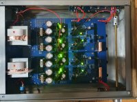
Heres my latest iteration for this awesome buffer whichs now my reference unit.
Purely passive psu, lrclrclrc string. Its output is... +-22v! (Gasp)
I doubled all the resistor values on the buffer to accomodate that and so theyre all either 2k or 270ohm. Still using bc327 337. The sound is much better than anything that came before it. If you ask me now id have to say regulators are overrated.
The kuartlotron doesnt thump anymore either at powerup with these new resistor values. Dc offset is still 1mv range and stable.
Id like to know tho if ive chosen optimal resistor values, and if psrr has been increased because of it.
P.s. used faston shielded inductor for this build. Like i said, it sounds flawless 😊
Attachments
At those voltages thermal coupling may be desirable between transistors. If you thermally couple them you will likely have to re-trim.
The regulators were more to keep the voltage in the optimal range for performance with varying power sources, but it sounded fine without them. I didn't go above 10V because it would always sound harsh.
The regulators were more to keep the voltage in the optimal range for performance with varying power sources, but it sounded fine without them. I didn't go above 10V because it would always sound harsh.
Fiddling with so many builds and schematics for my modular preamp ive come to associate bc327/37 with a bit of a 'zing' character. Its pleasantly bright but you couldnt really call it refined. In the past i had better results with bc550/560 like the others here have reported but the holy grail i bet is probably ztx851/951. Will try them and report back 😎
- Home
- Source & Line
- Analog Line Level
- The Kuartlotron - keantoken's simple error-correction superbuffer