I my opinion those and the coupling cap I would prefer not be on the board. These three things are the three most often modified. They are experimented with until the best combo is agreed on. Remember the B1 and how much experimentation was done until most agreed on coupling caps, psu and psu voltage? Leaving these parts out will eventually make this a better circuit.
No AFAIK it was Nelson Pass who presented a complete working B1 design with a PCB that included an onboard PSU. B1 was a success. I do remember the better DCB1/Mezmerize and it's success. It also has everything onboard and started off with an onboard PSU too. Yeah I know I was stubborn then to refuse shunt PSU's ") Thankfully they still made it into the final design. I am not so sure who wants to modify well designed stuff and uses 4 different separate PSU's to find out which one is the best. It is the task of the designer to make those decisions and test a device with various PSU's and offer the best possible performance. IMO many builders just want a functioning well measuring and well sounding device that is complete and usable in everyday life. After some GB's I can conclude that most builders want a "much better sounding than commercial gear" complete device that just works, the modders are the minority (by far!).
Thankfully they still made it into the final design. I am not so sure who wants to modify well designed stuff and uses 4 different separate PSU's to find out which one is the best. It is the task of the designer to make those decisions and test a device with various PSU's and offer the best possible performance. IMO many builders just want a functioning well measuring and well sounding device that is complete and usable in everyday life. After some GB's I can conclude that most builders want a "much better sounding than commercial gear" complete device that just works, the modders are the minority (by far!).
Should the input cap dangle in the air or something ? What power supply will be used ? If one is onboard the design can be used straight away. If one decides on a better supply it can be used too. No power supply at all means separate PCBs (where to find a +/- 10V good PSU PCB ? ...Ebay ?) with additional wiring or a soldered buffer board that has no use and stays in a drawer. This is reality for many builders and certainly for those that are not very experienced. If we like this hobby not to die out we need to offer well designed good functioning devices to younger people that start with audio with no added hassle and incompleteness. A readily reproducible device has most success and maybe some will mod it/improve it which possibly results in again a successful rev. 2 board. Modular thinking is very 1990's.
A poll would be nice to check what most builders want
Thankfully they still made it into the final design. I am not so sure who wants to modify well designed stuff and uses 4 different separate PSU's to find out which one is the best. It is the task of the designer to make those decisions and test a device with various PSU's and offer the best possible performance. IMO many builders just want a functioning well measuring and well sounding device that is complete and usable in everyday life. After some GB's I can conclude that most builders want a "much better sounding than commercial gear" complete device that just works, the modders are the minority (by far!).Should the input cap dangle in the air or something ? What power supply will be used ? If one is onboard the design can be used straight away. If one decides on a better supply it can be used too. No power supply at all means separate PCBs (where to find a +/- 10V good PSU PCB ? ...Ebay ?) with additional wiring or a soldered buffer board that has no use and stays in a drawer. This is reality for many builders and certainly for those that are not very experienced. If we like this hobby not to die out we need to offer well designed good functioning devices to younger people that start with audio with no added hassle and incompleteness. A readily reproducible device has most success and maybe some will mod it/improve it which possibly results in again a successful rev. 2 board. Modular thinking is very 1990's.
A poll would be nice to check what most builders want
Last edited:
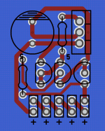
Ah, I tried to make a stereo with my first pcb layout but I do manage to something rational.For a first SMD design it looks good but why mono and why no power supply and volume control on the board ?
I will insist and we'll see!
DCB1 is exactly what I meant. There was a lot of DIY experimentation in the B1 thread before Salas decided to build a finished product. Nelson designed the B1, a well designed circuit, and it was tirelessly revised. In my opinion you dont runn off and order 100pcs of board no one has listened to yet. There was a lot of experimentation on DCB1 thread as well. For instance 50mA vs 120mA etc. But youve read the thread.
Last edited:
In my opinion you dont run off and order 100pcs of board no one has listened to yet.
When we did Subbu V3 we changed the design numerous times, I revised the DAC hardware n times and I stopped counting after 50 board revisions (small and large)....We did the testing, the measuring and the listening with no one else involved. Many hundreds of them have been built. Still requests for new boards....so IMO it is possible but it is a burden for the designer and eats lots of time. It depends how one defines quality... We decided on taking the difficult road and still do. We were sweating when the GB counter said we should order 500 boards. My recent SBT PSU made it to 150 pieces after only 2 beta testers and myself had tested it.
DCB1 was a group effort really. Salas designed the shunt supplies. Running more current was possible without any change to the PCB. I was heavily interested in the design and was actively involved. I made quite a few of them and still have a Mezmerize in use today. AFAIK boards were produced in numbers after just a few members had built one. I didn't know of countless revisions of the original Pass B1 except for those that do cap rolling but I would not call that revisions. To my knowledge Nelson does all the work in his lab and then presents a working product without glitches etc. so in the same line of thinking if I may say so.
Last edited:
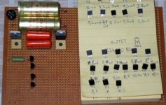
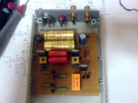
Just for the record, DCB1 was born as a personal project idea in 2008 during a why not DC path argument I put in the Pass B1 thread. Off I went to make a perfboard prototype with LM317-337 to test offset and general behavior. I even tested various rail voltages, pot types and values, it also included the output relay circuit. I was happy with the outcome. All that was done "live".
Jean-Paul spotted the DCB1 idea potential and even pushed by opening a thread for it so to call people's attention to that circuit. I shortly came up with a package design that included dedicated LED ref shunt regs so to try extract even more quality. A couple home etch attempts from members gave positive feedback to the design as a whole.
Then some people wanted to can build an official & finished one. I looked into it even further asking people if they wanted input switching, delay relay etc. Half said yes, half said no, so two versions I decided. One fully equipped and one single input.
First GB attempt was postponed after a volunteer to do the Eagle layout under my guide and then undertake the PCBs distribution left the scene. When the layout was ready and we showed the sketches he got apparently scared by the sheer number of interest that built up fast and went missing in action.
Disappointment lasted a while among the people until two "heroes" came forth on their own initiative to volunteer save the attempt. Namely CRT to do the CAD all over again and Tea-Bag to do the distribution. The weird z spelled names Hypnotize and Mezmerize came from album names of CRT's favorite band SOAD. Rest is history.
Attachments
Best possible summary, thank you Salas. I think I was one of the advocates to promote the use of input switching with relays (and against shunt supplies ) but I can't find the thread anymore I still think of it as a group effort started by you and a lot of positive energy added by various members that evolved in the Mesmerize/DCB1 PCB's. Against all odds Mesmerize boards can still be bought from the Store. It was that project that made me do my GB's.
As ex-mod and you still being mod I think the next line should be: back to the Kuartlotron design....
While we are at it: do you allow the use of your shunt supplies as used in the Mesmerize/DCB1 for this circuit ?
) but I can't find the thread anymore I still think of it as a group effort started by you and a lot of positive energy added by various members that evolved in the Mesmerize/DCB1 PCB's. Against all odds Mesmerize boards can still be bought from the Store. It was that project that made me do my GB's.As ex-mod and you still being mod I think the next line should be: back to the Kuartlotron design....
While we are at it: do you allow the use of your shunt supplies as used in the Mesmerize/DCB1 for this circuit ?
Last edited:
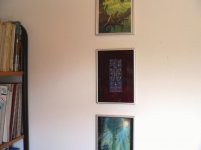
Maybe you were the most insisting one but many others went meh... we already got mechanical switches and/or already wired preamps to only drop in the module blah blah. So I went for two versions. After a while as we did various experiments with parts and current levels back and forth with people opining in the threads we respinned the single input one as to more hot-rod friendly and diversified its cap vref filter choice so to at least have more application in the "purist" camp. I went on with many nice PCB details instructions torturing it for a month. I will not forget one Dutch member that literally hanged one of the first DCB1 BLUE HOT-ROD boards as living room art.
Attachments
Maybe you were the most insisting one but many others went meh...
I was. It is therefore nice to see that that one survived and can still be bought. But to rephrase the question: can the power supplies as used in the DCB1 also be used in this design with your permission ?
Last edited:
While we are at it: do you allow the use of your shunt supplies as used in the Mesmerize/DCB1 for this circuit ?
Kean is a fine young DIYer with originality and ethos. So he already wrote to me asking and I replied to him that he can adopt those supplies on my permission.
Here is the shunt so far. Flat LEDs make for a less quirky, more compact layout. I'm trying to make it small so there is room for dual mono, but I'm not sure that can happen.
DC coupled?
Dual mono power, IE separate regulators for left and right. It might be possible if I move the pot quite a ways over, but that would deviate from the original board significantly. Then again, the exact positioning of the POT on the original board is unspecified, so I can't really put it in the right place anyways.
Make the LED pads dual purpose to suit both through hole and smd.
What size SMD?
Standard LEDs - SMD | Mouser
- Home
- Source & Line
- Analog Line Level
- The Kuartlotron - keantoken's simple error-correction superbuffer