Belgium?
Nope, but correct continent.
It seems Belgians have similar reputations as Bo....... here.

This last set of changes are rather neat, Project - not much to add from me
Maybe one thing - that test point is a bit hidden away and if stacked, as 'kt' intimated, would be awkward
Okay, "two birds, one stone" (a challenge for the translator!) -
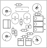
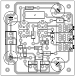
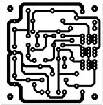
Move C1 up and to the left, move R11 horizontal above R1 so it jumps the 2 tracks and put TP where C1 used to be.
Move C2 to the left also, and reduce board size so trimpots are now close to edge of board for easy access for adjustment (maybe side adjust pots) - this makes stacking the boards easier.
That's about it, yes?
C2 on sika's board? a misprint, I think - R5, Q1, etc are connected to the -ve rail - you've got an 'eagle eye'!
Your C2 is correctly marked - I think I'll try some Nichicon BPs for these, as done previously.
Maybe one thing - that test point is a bit hidden away and if stacked, as 'kt' intimated, would be awkward
Okay, "two birds, one stone" (a challenge for the translator!) -
Move C1 up and to the left, move R11 horizontal above R1 so it jumps the 2 tracks and put TP where C1 used to be.
Move C2 to the left also, and reduce board size so trimpots are now close to edge of board for easy access for adjustment (maybe side adjust pots) - this makes stacking the boards easier.
That's about it, yes?
C2 on sika's board? a misprint, I think - R5, Q1, etc are connected to the -ve rail - you've got an 'eagle eye'!
Your C2 is correctly marked - I think I'll try some Nichicon BPs for these, as done previously.
Move C1 up and to the left, move R11 horizontal above R1 so it jumps the 2 tracks and put TP where C1 used to be.
It's a very good point!
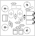
After all these changes the plate is 4.3 cm x 4.2 cm and I think I can not make changes.
My only problem is the inductance because for 2UH a coil would be too large and a molded inductor is a solution
To be continued!
Oops! I forgot to move the three trimmer to the edge.
Attachments

Last edited:
You could perhaps run the R5 <-> C1 track under R11 also if you move the R1 pot a couple mm to the left
Another way would be to move the right hand pad of the R11, and the TP donut, up a couple of mm - would need a small bend in the leg of the resistor when assembled and look a bit untidy on the pcb but would work quite well and allow trimmer pots right on the edge of the pcb
I like the large size donuts as I'm often changing parts and the small donuts often used, sometimes with vias, are neat and everything, but usually just the 'one shot' assembly (replacing components is often a disaster)
I'm a bit paranoid about this vias business and especially around electro caps, I know, and on an F5 pcb I went to the extreme of cutting a lot of the tracks (just used the donuts for mounting) and used the component leads for connections - a sort of p-to-p hybrid pcb - darn thing did sound better, would you believe!
I don't mind the 'normal' component inductor but 'sika's' pcb inductor is intriguing - new one for me in diy boards
Oh! I thought of something - again, sorry!
On C3, I would like to try one of those axial (?) styrene caps with the wires each end - could you move the track R2 <-> Q1 and add an extra donut on the left hand side of the existing one - they're those 'spindly' little clear plastic round caps with the wires coming out off-centre (getting a bit 'up-myself' now with special requests!!)
Don't forget to add a name somewhere, too ...
Hello all!
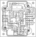
I have made some changes on the drawing.
- Trimmers tabs are compatible with many models.
- Ability to add a 1N4148 diode in connection with the commentary of keantoken
What are the values (normalized) for maximum trimmers R1, R5, R9.
Thank you!
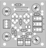
I have made some changes on the drawing.
- Trimmers tabs are compatible with many models.
- Ability to add a 1N4148 diode in connection with the commentary of keantoken
Small question:keantoken said:It does not start properly
I have not had problems with this after my final build. However it is possible that Q2 may never turn on due to there being insufficient leakage from Q1 and Q3 to turn it on.
Fit a 1N4148 across the B-E junction of Q1, pointing towards the emitter. If this does not work, then there is a fault elsewhere in the circuit
What are the values (normalized) for maximum trimmers R1, R5, R9.
Thank you!
Attachments
If you were to move Q2 & Q4 closer to Q1 & Q2, easy to connect together with a small copper strip - possibly not necessary, I know, but ...
'could solder R2 and D1 underneath the board to 'open up' the area - in fact, if you moved R2 up a bit, you could shift D1 horizontally besides C3 and if the track from bottom of R2 was moved away from pad for C3, there's room for an extra pad for using a larger C3 for other than Wima type 15pF cap there - also, if the two tracks under R2 are close enough, could use a 56R smd resistor for R2
There's enough donuts below the trimmers to allow a parallel resistor - for 56R trimmer, could use 100R trimmer with a 150R resistor in //, for example - extra flexibility - even for smds - neat idea, that one.
Hello!
This type of inductor is suitable or not?
MISC 2µ: Miniatur Funkentstördrossel, 2µ bei reichelt elektronik
https://cdn-reichelt.de/documents/datenblatt/B400/DS_MISC.pdf
Thank you!
This type of inductor is suitable or not?
MISC 2µ: Miniatur Funkentstördrossel, 2µ bei reichelt elektronik
https://cdn-reichelt.de/documents/datenblatt/B400/DS_MISC.pdf
Thank you!
Hello!
This type of inductor is suitable or not?
MISC 2µ: Miniatur Funkentstördrossel, 2µ bei reichelt elektronik
https://cdn-reichelt.de/documents/datenblatt/B400/DS_MISC.pdf
Thank you!
Yes, I think it will be fine. Unfortunately I never received a notification email for your post so I wasn't able to respond quickly.
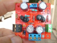
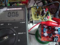
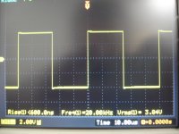
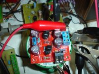
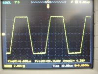
In the real life.
+/-10V Power supply
00.6mV Offset.
+/-10V Power supply
00.6mV Offset.
Attachments
-
 DSC09047.JPG550.7 KB · Views: 640
 -
 DSC09069.JPG579.9 KB · Views: 612
 -
 DSC09060.JPG532.1 KB · Views: 162
 -
 DSC09056.JPG592.1 KB · Views: 146
 -
 DSC09055.JPG582.1 KB · Views: 138
 -
 DSC09054.JPG607.5 KB · Views: 139
 -
 DSC09052.JPG534.7 KB · Views: 157
 -
 DSC09050.JPG521.3 KB · Views: 512
 -
 DSC09049.JPG537.2 KB · Views: 559
 -
 DSC09048.JPG587.4 KB · Views: 579
Last edited:
Thanks,i will try this soon.It seems C2 has wrong polarity on my board. Please reverse.
BR Sika
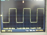
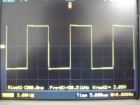
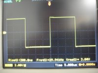
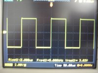
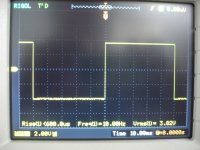
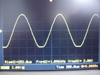
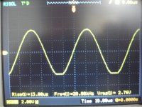
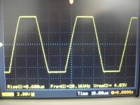
Now i remember that is a strange way that( - power supply ) response.
So all is ok.Clipping is asymmetrical by nature but it doesn't matter. Thanks for testing it out.
This is a good news!
Just a question,where is the best position to connect a volume potentiometer,and what value?
If your destination is a power amp, putting the buffer after the volume control can be a big improvement.
If your source sounds better with high-impedance loads, using a low-value volume pot (5k-10k) after the buffer will help with that as well as provide a relatively low source impedance for your destination.
If your source sounds better with high-impedance loads, using a low-value volume pot (5k-10k) after the buffer will help with that as well as provide a relatively low source impedance for your destination.
Thanks,for all the hard work!If your destination is a power amp, putting the buffer after the volume control can be a big improvement.
If your source sounds better with high-impedance loads, using a low-value volume pot (5k-10k) after the buffer will help with that as well as provide a relatively low source impedance for your destination.
- Home
- Source & Line
- Analog Line Level
- The Kuartlotron - keantoken's simple error-correction superbuffer