Ah, right - simple.
I had another question about your webpage that I can't figure out and wondered if it's a misprint - this is just below the diagram of the 'ideal transistor' - the underlined bit
The mechanism that causes this result is surprisingly simple - Since Ic(Q2) = Ic(Q4), Vbe(Q2) = Vbe(Q4). Similarly, Ic(Q1) = Ic(Q2), so Vbe(Q1) = Vbe(Q3). Since Vbe(Q3) = Vbe(Q4), this means Vbe(Q1) = Vbe(Q2), which is to say, the Vbe of Q1 is directly cancelled by the correction signal across Vbe(Q1).
Thanks ... James
Oops, that needs to be corrected. It should be
... the Vbe of Q2 is directly cancelled by the correction signal across Vbe(Q1)
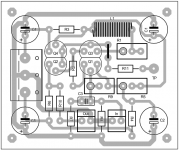
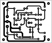
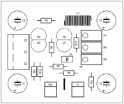
I like the first one best (left hand design) with the more symmetrical arms to the power caps and the way you've separated the IN & OUT ground pins - R7 & R8 belong to this current path, not the power supply tracks, and moving R2 upwards fixes R7, but R8 not so easy - another way would be to exchange R7 and C3 positions, and also exchange R8 and IN terminal and push up that R8 into a new gap created between R9 & R5 .... interesting, eh!
You could perhaps squeeze the R11 vertical instead of the link - might need to alter tracks around R9 but quite 'do-able' - you might add a bit more clearance on the C4 & C5 caps.
I wonder if the IN & OUT terminals could be brought a bit closer to the board's edge - the track R6 to R4 is the problem - the only way I see around it is to put the R4 underneath and use it 'stretched out' as a link to a donut next to R6, but not very pretty and subject to mistakes - hmm!
As this is just the single channel, I wonder if it's worth looking at adding another mirror image buffer (with appropriate transistor adjustments) on the left hand side of the power input terminal for a stereo buffer and you wouldn't need to duplicate the caps C4 & C5 - just an idea (the pots R1, R5 & R9 make it impractical to stack them on top)
As 'kt' mentioned above, you could add a 2nd layer that would replace the capacitor return tracks and provide ground plane merits, but with this simple design, we could make these boards at home
I have a habit of squeezing components a bit closer together - you could perhaps do the same here - it looks to be about 60 x 50 mm at present?
Looking good, IMO
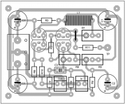
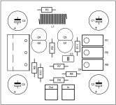
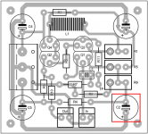
To shorten a little some tracks I have changed the connections to the pads trimmers, the rotation does not matter I think. I also made a small change on the ground track of R7 and R8.
Attachments
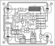
Looking rather neat now - like that track for the R7 & R8
Maybe have another look at the trimmer pots, at least R1 & R7 anyway - turning the adjust knob clockwise will increase 1 trimmer but decrease the other - perhaps it might be worth making them consistent
Apart from that it seems to be pretty complete - any thoughts about maybe a stereo version - if you were to add this to the 'DirtyPCB' list, a double sized board would cost maybe U$25, instead of the basic U$14, and complement 'sikahr's' boards well.
... later
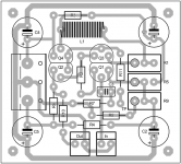
The change to R7 and R8 was good. R7/C3 should be in the shortest path between ground and Q1.
The input and output connectors have ground on opposite sides. This encourages hookup mistakes.
As for stereo boards, I would prefer to have 2 mono boards and just stack them using standoffs. Is lack of vertical space the main consideration here for others?
I was thinking that if I had Project16's permission I'd like to base my own Kuartlotron PCB on this layout, adding a ground plane system and a PCB inductor.
The change to R7 and R8 was good. R7/C3 should be in the shortest path between ground and Q1.
The input and output connectors have ground on opposite sides. This encourages hookup mistakes.
As for stereo boards, I would prefer to have 2 mono boards and just stack them using standoffs. Is lack of vertical space the main consideration here for others?
I was thinking that if I had Project16's permission I'd like to base my own Kuartlotron PCB on this layout, adding a ground plane system and a PCB inductor.
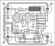
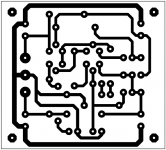
I made these changes on your advice but it is very difficult!
Is that better?
You can use this track for your pcb without problem, you need it?
Attachments
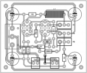
I have a way to get rid of that link - I'll see if I can describe it clearly enough ...
Okay - for now, get rid of the 'power track' between R4 from C5 below the OUT and IN terminals. Move the OUT terminal down into this new space and now run the fat ground track from the OUT terminal to the In terminal where the 'power track' used to be (now runs under the IN terminal itself) - now there is no need for the jumper but what to do about that discarded 'power track', eh?
Move the R4 so it sits horizontally above both IN and OUT terminals (stretches across the new track where the link used to be) connect it back to C5 as before (need to lift/move the fat ground track a bit) - the right hand side of R4 again connects to C2, R9 as before - saves a bit of space too!
Suggest you consider changing the centre donut to connect to the right hand side donut, not the left hand side, of R5 unless I'm missing something ....
'KT', when you stack these 2 buffer boards, you can't get access to the trimming pots or the screw terminals - maybe use trim pots with 'side adjustment screw' and once the boards are wired up, you don't need easy access to them, so I guess stacking could work just fine - maybe the dual boards aren't really necessary after all.
For the double sided pcb, that pcb choke seems rather attractive idea - enough room?
Couldn't find a 'raw dc power pcb at 'DirtyPCB' - maybe missed it - the diyAudio Store has one at U$29 - not really suitable for the buffer, etc - might have to do our own, maybe ...
Couldn't find a 'raw dc power pcb at 'DirtyPCB' - maybe missed it - the diyAudio Store has one at U$29 - not really suitable for the buffer, etc - might have to do our own, maybe ...
James, I didn't yet post raw DC to DirtyPCB. I will post 10x8 PCB when it will be ready, for a few days max I expect. Their price for <10x10cm boards prototype pack 10+-2 pieces is 25$ with free shipping.
@jameshillj:
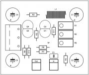
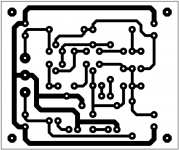
With an online translator is not easy!
A few changes but it's really difficult to get connections as short as possible with this small area (new dimension: 4.8cm x 4.4cm).
With an online translator is not easy!
A few changes but it's really difficult to get connections as short as possible with this small area (new dimension: 4.8cm x 4.4cm).
Attachments
Hi i was also thinking of a board layout for this buffer despite being switched to DDX amps. Can not forget analog completely I see some of you have designs in the works.
Some suggestions to incorporate on the PCB:
- a stereo PCB would be optimal as most will use a stereo setup (I hope).
- power supplies onboard would make wiring less complicated. Salas shunt supplies like those on DCB1 Mesmerize come to mind. Those are +/- 10V.
- Eh.....7810 and 7910 do exist....and nowadays they are better than they used to be in the past.
- a simple micro muting relay shorting outputs to GND during power on sequence. You never forget the smell of burned woofers
- Pads for a volume potentiometer (combined with pads for a connector block) would be nice too.
- CLC filtering to and from the regs would be the icing on the cake. Just 2 regs with separation done by CLC filters to each channel that is.
- GND plane
- inputs and outputs at opposite sides of the PCB as it would make wiring to the output RCA connectors easier. Inputs can stay where they are now, they can be combined with pads for a volume control.
- Double sided PCB would make the board smaller
- SMD coil for the 2 µH coil.
- Relay input switching would make it a mutant Mezmerize clone but what the heck...
One board solutions are (back to) the future !!
I see some of you have designs in the works. Some suggestions to incorporate on the PCB:
- a stereo PCB would be optimal as most will use a stereo setup (I hope).
- power supplies onboard would make wiring less complicated. Salas shunt supplies like those on DCB1 Mesmerize come to mind. Those are +/- 10V.
- Eh.....7810 and 7910 do exist....and nowadays they are better than they used to be in the past.
- a simple micro muting relay shorting outputs to GND during power on sequence. You never forget the smell of burned woofers
- Pads for a volume potentiometer (combined with pads for a connector block) would be nice too.
- CLC filtering to and from the regs would be the icing on the cake. Just 2 regs with separation done by CLC filters to each channel that is.
- GND plane
- inputs and outputs at opposite sides of the PCB as it would make wiring to the output RCA connectors easier. Inputs can stay where they are now, they can be combined with pads for a volume control.
- Double sided PCB would make the board smaller
- SMD coil for the 2 µH coil.
- Relay input switching would make it a mutant Mezmerize clone but what the heck...
One board solutions are (back to) the future !!
Last edited:
@jameshillj:
With an online translator is not easy!
 I am not Chinese but I know my English gramar is awfull
 Try to guess my home country.
+1 for the stereo version. No reason not to have mono and stereo versions on Dirty . Also, would be nice for those with different power supplies to make onboard provision for the shunt regulators or 7810/7910.
PCB inductor can be on bottom layer of a 2-layer board can it not? Surrounded by a ground plane as mentioned above.
Sounds like a good way to get the Kuartlotron into widespread use, kt....
. Also, would be nice for those with different power supplies to make onboard provision for the shunt regulators or 7810/7910. PCB inductor can be on bottom layer of a 2-layer board can it not? Surrounded by a ground plane as mentioned above.
Sounds like a good way to get the Kuartlotron into widespread use, kt....
Hello everyone!
I have two questions.
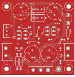
- What is the correct position of C2?
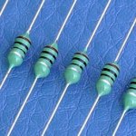
- A self molded like the image it may be appropriate?
Thank you!
I have two questions.
- What is the correct position of C2?
- A self molded like the image it may be appropriate?
Thank you!
Belgium?Try to guess my home country.
Attachments
- Home
- Source & Line
- Analog Line Level
- The Kuartlotron - keantoken's simple error-correction superbuffer