Kean, permission to post on Dirty?
Kean granted permission for a publication. There was no mention of sales.Go ahead.
Selling for profit is outside the scope of their original agreement.
Example: If I told someone they could borrow my car for a day, it would be a bad surprise if they sold it instead.
Last edited:
.................maybe every other week he will be able to afford a gumball at the corner store.
Exactly - The real point is that he is doing a great service.......those in penury can always sell a few in the back pages; and, perhaps, even make an enormous profit.

")
Yeah, but not for each board, just for each order, which is no less than 10 boards. So maybe every other week he will be able to afford a gumball at the corner store.
Hey, you underestimates sales potential of this boards.
Not only I am on permanent vacation now, I am thinking about investment in gold or something.

I like that one. To reduce the field of some of the traces I would add a ground plane connected to nothing but power ground. Or just cover the bottom in aluminum foil with a sheet of paper in between, if the board has to be single-sided.
+-15V is possible but may not sound right and have higher distortion.
The TL431 used as a shunt regulator is sufficient to meet the needs of the Kuartlotron.
+-15V is possible but may not sound right and have higher distortion.
The TL431 used as a shunt regulator is sufficient to meet the needs of the Kuartlotron.
Last edited:
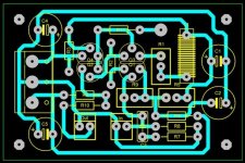
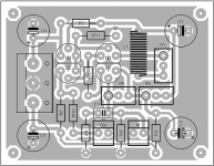
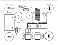
Perhaps a simple link from the power supply input terminal block to the midpoint of the C1, C2 ground connection, straight down the centre of the board beside R5, R9 - this gets rid of the long 'ground return' track around the outside past C4
If you don't mind re-arranging the board a bit, move the TP to next to the R3 position and reconnect R11 above Q3, as this allows room to move the L1 up to below the top track where the TP donut was, move R1 below it ( horizontal) and this opens up the corner to move R5 up where R1 used to be - a bit shorter tracking - not sure if much benefit as this is power supply
(could also move R3 to horizontally above Q4 but a bit of a squeeze with new TP)
Another not so easy one would be to move R4 to between R9 and the 'IN' terminal & C3 - in fact, could nearly swap positions of 'IN' terminal and the R7 & R8 - this would simplify ground return loops
I think 'sikahr' focused more on the ground tracking rather than your more dense component layout - be interesting to see if there's a difference in the 'sound' of the different layouts - what are the measurements?
Thank you for your answers!
I modified my circuit but it is very hard to beat for me while maintaining a very compact size and one side.
The possibility of double-sided with a ground plane is also a solution with this drawing.
Thank you!
I modified my circuit but it is very hard to beat for me while maintaining a very compact size and one side.
The possibility of double-sided with a ground plane is also a solution with this drawing.
Thank you!
Attachments
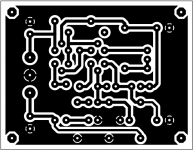
Project16, your ground layout is now causing ground noise because of the voltage gradient through the plane between ground points caused by capacitor currents. This is why I described a second layer ground plane connected to nothing but power ground (the single power ground connector, and nothing else). It would be better to keep the original ground scheme, separate from the ground fill, which again is connected to only a single point.
Got the dirty boards...
What should be the ideal V+- to power them ?
The original +-10V as specified, unless Sikahr made unannounced modifications.
got the dirty boards also and built two of them already. They worked right away and made no problems
I briefly tested them with the unbuffered output of the dam1021 and they sound great!
I have to listen more, but they did something very nice into a low impedance (3,3k ohm) input of a irs2092 amplifier. Maybe that is just logical, because the dam has a output impedance of 625 ohm and the kuartlotron just does what has to be done, but still, I think they sound better than the buffered output of the dam, which is a regular opamp affair.
Thanks a lot for the the design and I hope keantoken has no problems with the dirty pcbs.
I used the internal inductor, seems to work just fine.@Hop.sing
Thanks for building the board, I am glad they are working good
Internal or external inductor?
As 'kt' said in post #234, and if I've got this right myself -
a second layer ground plane connected to nothing but power ground (the single power ground connector, and nothing else
There are the 4 capacitors ('-ve/+ve) to the central 0 volt point on the 3 pin terminal block via this ground plane (I don't like ground plane power supply return paths, myself, but ..) and then there's a separate track to this same pin from the group of R7, R8 and the IN and OUT terminals - even in this simple ground scheme, these some design considerations!
Now, as this central ground goes to the central 0 volt point of the power supply and usually continues out to the transformer, does this get connected to chassis earth point directly, or via a 'floating resistor' for a 'ground loop breaker', and where is it attached - remember, the IN & OUT ground terminals are also connected to the signal IC shield mesh and directly to the associated 'stages'
A question - If the continuous ground plane is used, should it continue above/below the planar inductor, or avoid this area?
New territory for me, and it doesn't appear to be at all significant in this circuit and more of a design question, but does any 'noise' from the power supply, or the IC shields (if you use them) get transferred to the ground plane and back into the active circuit this way and do high frequency rules, etc, still apply here ?
It would be a good thing if the plane shorts out the portion of the inductor's field that passes through other components. This way there is less interaction with potentially nonlinear magnetic materials like leads, screws, etc. Better yet, put the inductor on the opposite side of the ground plane to the components so the plane is between them. I don't think the bulk of the magnetic field will pass through the plane so I don't think there will be a problem with the inductance changing.
- Home
- Source & Line
- Analog Line Level
- The Kuartlotron - keantoken's simple error-correction superbuffer