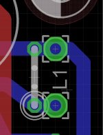
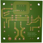
For convenient build, can you do L1 with PCB traces?Only cosmetic changes, if there are no compalints I'll post this to dirty tommorow...
Yes I can ")
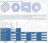
Anybody knows how much uH is this inductor?
Calculation is for 20x20mm=2.9uH and ours is 20x16mm, so I believe we are not very far from 2uH.
Please someone check this independently.
Calculator link: Planar spiral coil inductor calculator
Anybody knows how much uH is this inductor?
Calculation is for 20x20mm=2.9uH and ours is 20x16mm, so I believe we are not very far from 2uH.
Please someone check this independently.
Calculator link: Planar spiral coil inductor calculator
Attachments
Last edited:
Kean, permission to post on Dirty?
Go ahead.
the number of Turns and the Area enclosed within the "coil" are the two major factors affecting the inductance value............Anybody knows how much uH is this inductor?
Calculation is for 20x20mm=2.9uH and ours is 20x16mm, so I believe we are not very far from 2uH.
Please someone check this independently.
Calculator link: Planar spiral coil inductor calculator
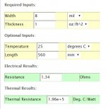
I am not familiar with the calculation, nor the flat type of inductor, so this is off the top of my head:
The area inside the 20 by 16mm coil is similar to a 18 by 18mm coil.
If you input 18mm into the "square" calculator you should get a close approximation to what the calculator designer would expect.
A wire coil has inductance that depends on Turns and the effective diameter of the "wire group".
If the coil is not circular, i.e. it is puled out into an oval, or into rectangle, then the inductance drops. This drop would be because the non circular shape encloses a smaller Loop Area.
That is the same effect as your 18x18, compared to 20x16.
Does any of that make sense?
Hi Joachim,…
I compared the Calvin against the Kean. Well., Martina may be able to describe that better.
…
Would you care to say which one you prefer, or a brief account of the differences between those 2 buffers?
Thank you.
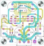
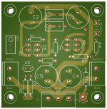
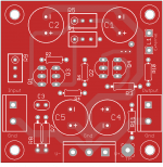
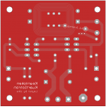
For flexibility I decided to put it this way:
* added pads for external L1 conected serial with internal L1.
This way you can use internal, external or both L1, just short one you dont want to use.
If nobody complaints this version is final.
Many thanks Kean.
Andrew, it makes perfect sense to me, but I really dont have knowledge to be sure, so I added "backup" plan with external L1, this way if internal is OK all is good, if not you can use external L1.
* added pads for external L1 conected serial with internal L1.
This way you can use internal, external or both L1, just short one you dont want to use.
If nobody complaints this version is final.
Go ahead.
Many thanks Kean.
Does any of that make sense?
Andrew, it makes perfect sense to me, but I really dont have knowledge to be sure, so I added "backup" plan with external L1, this way if internal is OK all is good, if not you can use external L1.
Attachments
Last edited:
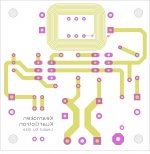
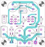
Work in progress, more or less finished...
Kean, please take a look & comment
I'll continue tomorrow, must to go...
You did it - only 2 days vacation
//
Member
Joined 2009
Paid Member
Very nice work K.
It seems to me that the approach taken by this buffer topology is also applicable to half / full Diamond Buffer output Power Amplifiers... I wonder if Hawksford tried something ?
But I'm not sure I agree that this circuit doesn't use feedback. The CM is the feedback mechanism, only it senses current of the output device instead of voltage (nothing wrong with that). Anyhow, it's only semantics.
Last edited:
Attachments
Aha! I see what you did there.
Maybe I'll try that in the future too...
http://dirtypcbs.com/about.php said:Share and sell your PCBs with DirtyPCBs!
Have a design you want to share or sell, but don't want to keep stock, print labels, stuff envelopes, and walk to the post office? Share your board in our store and optionally get $1 of Dirty Credit or cash for each order. On the status page click the 'Add to store' button and your PCB will be available immediately to all our filthy customers. Click the 'Get $1' button to enable a sleazy affiliate scheme. Credit can be used anytime, cash payouts are made by Paypal at a balance of $10 or more.
Maybe I'll try that in the future too...
Is this a clear cut case of theft, or will you pay Kean for His circuit design?Yea, you disclose my secret plan, damn
- Home
- Source & Line
- Analog Line Level
- The Kuartlotron - keantoken's simple error-correction superbuffer