At the moment I'm designing a balanced DCB1. While most of my gear has balanced in and outputs, some have only single ended outputs. For that reason I want to add some single ended inputs to be balanced DCB1. I'm looking for a good way to achieve this, without using expensive transformers.
After some reading on the web I came across this article from Walt Jung
http://www.analog.com/library/analogDialogue/archives/39-05/Web_Ch6_final_I.pdf
Look at page 67.
The schematic on that page shows an op-amp circuit used for single ended to balanced conversion. It does exactly what I'm looking for, but if I was to use such an circuit I'd like to use it with better op-amps, so if I change the OP275 for TI's LM4562 would the circuit still work?
Perhaps there are other (better??) ways or circuits to achieve single ended to balanced conversion?? Perhaps other op-amps that are better suited for the job, anything... I'm open to suggestions.
I'm looking for a high fidelity solution with reasonable pricing.
Perhaps the more easy can be the use of especifics IC's, as the INA134 and the DRV134:
http://www.ti.com/lit/gpn/ina134
http://www.ti.com/lit/gpn/drv134
Some examples:
Electronique - Realisations - Symetriseur audio 006
Electronique - Realisations - Desymetriseur audio 005
http://www.ti.com/lit/gpn/ina134
http://www.ti.com/lit/gpn/drv134
Some examples:
Electronique - Realisations - Symetriseur audio 006
Electronique - Realisations - Desymetriseur audio 005
I have converted my system to balanced {sowter transformers} and several other peoples systems; I did not think it would improve the Audio but it certainly makes them much quieter. another advantage is the better XLR connectors and you can run much longer leads.
My friends and Myself think it has made a big difference; mine is very minimal but one friend has everything balanced; cost a lot using transformers.
Phil
My friends and Myself think it has made a big difference; mine is very minimal but one friend has everything balanced; cost a lot using transformers.
Phil
Adding more amplification stage is not the goal, I'm just looking for a way to let the balanced DCB1 take both balanced and single ended inputs and output the signal to balanced outputs. I clearly see the benefit of balanced lines, so that's no point of discussion to me. Besides most of my gear has balanced in and outputs and I'd like to use these.What do you hope to gain by adding more amplification stages? If the source is single ended, adding more stages to convert the source to balanced will not improve anything.
Now back on topic; The only outputs will be balanced outputs for now, but maybe I will want to add some single ended outputs to make it a bit more versatile. That would mean that there must also be some sort of balanced to single ended conversion, but that is easier to achieve imho. So the big question is how to let the balanced DCB1 take both balanced and single ended inputs and output the signals to the balanced outputs in a way that does degrade the signal integrity as little as possible, but at a reasonable price.
These are the schematics for the balanced input --> buffer --> output
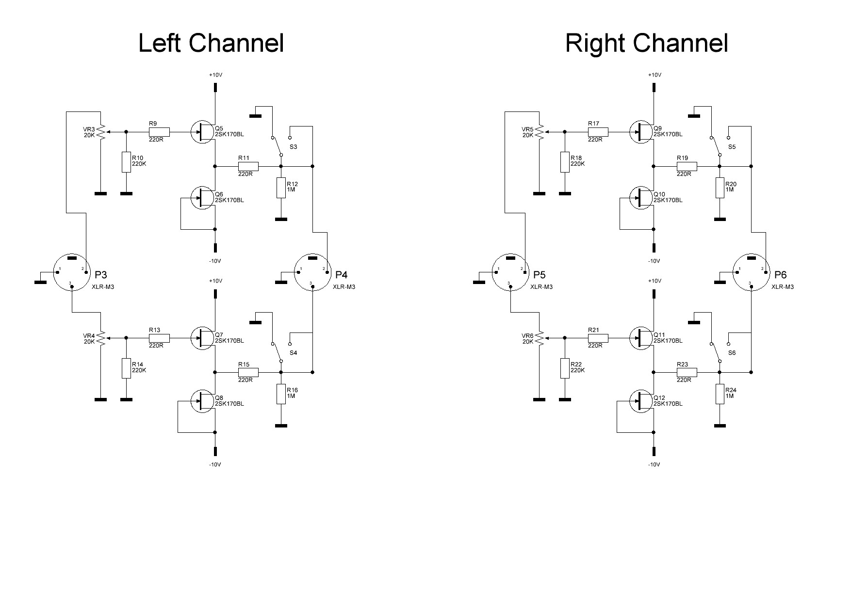
That's how you can connect single ended outputs to a balanced amplifier. The output will not see ground if I connect the negative input to ground because the buffer is in between.
I was planning to use a single relay to control the MUTE circuit of a single balanced channel. I could use two relays of course. When using a single ended input I can short the buffer's (negative) output to ground. This way the amplifier will also see ground. I think that this is what you mean, right?
I was planning to use a single relay to control the MUTE circuit of a single balanced channel. I could use two relays of course. When using a single ended input I can short the buffer's (negative) output to ground. This way the amplifier will also see ground. I think that this is what you mean, right?
That's how you can connect single ended outputs to a balanced amplifier.
is that not what it is

I was planning to use a single relay to control the MUTE circuit of a single balanced channel. I could use two relays of course. When using a single ended input I can short the buffer's (negative) output to ground. This way the amplifier will also see ground. I think that this is what you mean, right?
hmm, not sure, maybe
I meant that a multipole input selector might do double function and simultaniously switch to SE convertion when selecting to those sources
but yeah, maybe a simple relay is easier
on second thought, maybe it would wise to cut ground input as well as signal input for all sources, so that only the active input is grounded

(might take care of possible chassis/ground loop issues)
Yes, but I can not simply connect to ground to the negative input, right? With the buffer in between the buffer's negative output does not see ground or am I missing something here??
The negative output need to connect to ground, by means of a a multi-pole input selector or relay, while leaving the negative input open. But how does this effect the buffer if the output is shorted for a long time?
The negative output need to connect to ground, by means of a a multi-pole input selector or relay, while leaving the negative input open. But how does this effect the buffer if the output is shorted for a long time?
I was typing a reply while you where posting, so ...hmm, not sure, maybe
I meant that a multipole input selector might do double function and simultaniously switch to SE convertion when selecting to those sources
but yeah, maybe a simple relay is easier
on second thought, maybe it would wise to cut ground input as well as signal input for all sources, so that only the active input is grounded
(might take care of possible chassis/ground loop issues)
All input signals not used will be cut indeed, but I'm not sure if cutting their grounds is needed. It would make the input switching much more complex. Perhaps is connecting the negative output to ground the best solution. No op-amps/line drivers would be needed keeping the amount of parts in the signal path to a minimum.
What would happen if I connect the negative input to ground? Or would it be best to leave it open?
The drawing in post #6 is far from a balanced circuit. A balanced circuit (input or output) needs to be symmetrical. All the circuit caps & resistors need to be matched to 1%. Not individual pots.
Also on a XLR connector the pin #1 is only connected to the chassis near the connector, it is not part of the circuit common or ground.
Also on a XLR connector the pin #1 is only connected to the chassis near the connector, it is not part of the circuit common or ground.
pin #1 error solved.
There are no capacitors in the circuit path. The resistors are quite easy to match, but what do you suggest to attenuate the signal without using a pot? A logarithmic attenuator with resistors matched to 1% or even closer by using resistors from f.i. the RC55 series (0.1%) from Welwyn?The drawing in post #6 is far from a balanced circuit. A balanced circuit (input or output) needs to be symmetrical. All the circuit caps & resistors need to be matched to 1%. Not individual pots..
Attachments
Also on a XLR connector the pin #1 is only connected to the chassis near the connector, it is not part of the circuit common or ground.
really ? I thought pin-1 was signal ground in a true balanced system ?
and chassis/earth would be a 'partly isolated system'
(you will find info on how to do that in Pass F5 and F5Turbo threads)
but I find it strange that there is so little solid info to find in general
or that the available info is so 'contradicting'
Connecting unbalanced outputs (RCA or 1/4" Mono Jack) to balanced (XLR or 1/4" TRS)? - Powered by Kayako Help Desk Software
only problem using the cable itself to create the convertion ... the cable needs to be right
google search key ... RCA to XLR (and go to pictures in google menu)
only problem using the cable itself to create the convertion ... the cable needs to be right
google search key ... RCA to XLR (and go to pictures in google menu)
Hi,
There are schemes commonly used in studios to take advantage
of a balanced input when connected to single ended outputs.
Presuming hot is driven by the SE output, the cold input though
carrying no signal level, is used to cancel any common mode
signal equally induced on both the hot and cold in the cable.
Covered by Douglas Self in his books, presumably also others.
rgds, sreten.
really ? I thought pin-1 was signal ground in a true balanced system ?
and chassis/earth would be a 'partly isolated system'
(you will find info on how to do that in Pass F5 and F5Turbo threads)
but I find it strange that there is so little solid info to find in general
or that the available info is so 'contradicting'
There is no "signal ground" in a balanced system. Each signal line has the same impedance to ground in a balanced system. The shield may be grounded, but it is not a signal carrying conductor.
http://jensentransformers.com/an/an003.pdf
http://jensentransformers.com/an/generic%20seminar.pdf
Last edited:
- Status
- This old topic is closed. If you want to reopen this topic, contact a moderator using the "Report Post" button.
- Home
- Source & Line
- Analog Line Level
- Single ended to balanced conversion