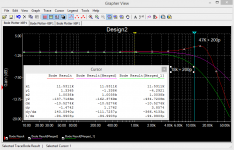
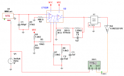
i simulated the 75uS response -- i don't think i will use a relay, just a molex jumper:
The simulation, fwiw, used the new transistors bob recommended, and the updated current mirror.
An externally hosted image should be here but it was not working when we last tested it.
The simulation, fwiw, used the new transistors bob recommended, and the updated current mirror.
")
Hi
Please alight me,
Damping mode mm means that passive 75us in the preamp is swiched off (D1,2 off)
and the cartridge is loaded with extra resistors to get the compensation for cartridge inductance from 200 to 700mH.
What value resistors connected parallel to input 100k resistors R1,2 (fig6 in LinearAudio vol 4) will get right damping for 200, 250, 300, 400, 500, 700mH?
Or damping was created electronicaly by adding inverting opamp with the gain 9 and via the resistors (470k) to Vin+ and Vin-?
Hi
Please alight me,
Damping mode mm means that passive 75us in the preamp is swiched off (D1,2 off)
and the cartridge is loaded with extra resistors to get the compensation for cartridge inductance from 200 to 700mH.
What value resistors connected parallel to input 100k resistors R1,2 (fig6 in LinearAudio vol 4) will get right damping for 200, 250, 300, 400, 500, 700mH?
Or damping was created electronicaly by adding inverting opamp with the gain 9 and via the resistors (470k) to Vin+ and Vin-?
It's been quite awhile since I've looked at that, and most of the information on calculating those loading (damping resistors) should be in the original LA article. In a nutshell, in damping mode, the 75us rolloff in the preamp is "stopped" at 8kHz, flattening the electrical response from there on up to higher frequencies. This means that the passive 75us is not switched off, but instead the relay is engaged to alter the 75us response so that it stops falling at frequencies above 8kHz. The damping resistor is chosen so that it creates a pole with the cartridge inductance at 8kHz. The value of the damping resistor should equal the reactance of the cartridge inductance at 8kHz.
Cheers,
Bob
Dear Bob
thank you,
1. how should I calculate the resistor value for AT 440MLa with the parameters:
DCR 776 Ohm
impedance@1kHz 3.2 kOhm
inductance@1kHz 490mH
2. calculated resistor value should be divided by 2 and putted instead of grounding input 100k resistors R1,2 (parallel with ~100p cables capacitance)?
I could be more specific, maybe my questions were too chaotic?
Anyway I do not understand about cartridge loading.
I read a text about VinylTrak @LAvol4 again and there was nothing about how loading selector is built, there was only that the selector sets the inductance: 200, 300, 400, 500, 700mH. There was no formula too.
Please explain me what values of the resistances and capacitances should be used in this selector?
thank you in advance!
thank you very much,
example for Shure V15 mk v:
2X3,14X8000Hz*0,37H=18597,68 Ohm
is this correct?
Hi
18k for Shure 15
but how about a capacitor in parallel, is it needed?
Is this answer suggesting that the V15/iv be loaded with 18k instead of 47k?
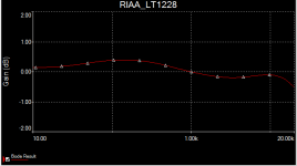
I believe that Bob calls it the "damped response" -- this relieves the first gain stage of the possibility of overload at 10kHz and up. He then compensates for the new curve in the RIAA amplifier.
Attachments
I believe that Bob calls it the "damped response" -- this relieves the first gain stage of the possibility of overload at 10kHz and up. He then compensates for the new curve in the RIAA amplifier.
Hi Jack,
Good explanation. The reduced load resistance brings one of the poles down in frequency so that it becomes real, allowing the addition of a zero into the 75us part of the RIAA response to compensate it.
Cheers,
Bob
I'm still confused. If you model the phonograph cartridge as a low pass filter the transfer function has two poles and no zeros. If you reduce the Q to 0.5 by reducing the load resistor the poles are coincident on the negative real axis. As you reduce the Q further one pole moves out on the real axis toward minus infinity and the other pole moves in toward the origin. However if you model the cartridge as a parallel resonant circuit there is a low frequency zero at Rs/L where Rs is the source (cartridge) resistance and L is the inductance. The zero is much closer to the imaginary axis that the pole and is going to dominate the low frequency response. I don't understand how that pole is going to have much effect around 2,200 Hz.
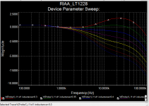
I swept the cartridge inductance from 300mH to 650mH with R1=18k
Hi Jack,
I like this data presentation. Quite revealing.
Cheers,
Bob
- Home
- Source & Line
- Analogue Source
- Bob Cordell's VinylTrak