opa2134 was far superior than any other opamp at high frequencie with crystal clear sound.(i had opa2134 in tone section and tl072 as preamp-buffer)
i will order some cause i only have one piece.
second place tl072.
4558D had a very good sound as well and i didnt expect it but i guess it has higher thd than tl072.
last one goes ne5532 it sounded very cold.
i will order some cause i only have one piece.
second place tl072.
4558D had a very good sound as well and i didnt expect it but i guess it has higher thd than tl072.
last one goes ne5532 it sounded very cold.
last one goes ne5532 it sounded very cold.
which op-amp that sounded hot or very hot?

The circuit of post 33 deviates from the normal active Baxandall topology in connecting series caps to the pot wiper rather than one in parallel with the full pot resistance. That may be undesirable as all input bias current flows through the bass pot, meaning the DC bias on C1, C3, and C4 can shift by millivolts depending on pot position.
maouna doesn't state test conditions or methodology but one could set up a model and have a look (I'm having a motivation fail on this and maouna's already got the circuit in LTSpice). It's likely this was a small sample size, sighted trial and the changeover time may have been longer than audio memory. So it's also possible the subjective result may not be significant.
maouna doesn't state test conditions or methodology but one could set up a model and have a look (I'm having a motivation fail on this and maouna's already got the circuit in LTSpice). It's likely this was a small sample size, sighted trial and the changeover time may have been longer than audio memory. So it's also possible the subjective result may not be significant.
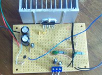
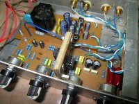
I know this thread been quiet for while just wanted to say thanks for the circuit Maouna I built this to use in my 6 yr old daughters amp I am building her.And also say it is very forgiving too I built it on a proto board and hooked it up to a tda7269a amp that it is gonna go with and no osscilations and very quiet too,and I had too use wires to attach the pots.Now to get a enclosure to put it in.Here are a couple pics of the tone control and power amp.1st is the tone 2nd is power amp.
Attachments
Sorry to wake an old Thread!
I've made similar tone control with this. I use TL074, sound is good.
Then I change the the OpAmp to 2x NE5532 (with adaptor), sound is better, more clear.
But I'm still thinking about the correct value for the feedback resistor in the 1st stage.
Q1 = input impedance of NE5532 is about 300k, and is stated as Open-Loop Test Condition in the datasheet. So, what is the internal input impedance of NE5532 if it has a Closed-Loop Gain of 2x ??
Now I'm using 100k & 220k (inverting) on the first stage. It's driven directly from a Pot (50k dual-gang Volume pot + 100k Balance pot).
I think the noise is quite annoying (both TL074/NE5532), because the power amp (LM1875T) itself is dead silent! I was thinking to lowering the feedback resistor value.
Q2 = If I change the feedback resistor to 47k & 100k, is it will make too much distortion because it is driven directly from Pot??
If you recommend me to change the volume pot to 10k or 25k dual gang pot, I can't do that, no electronic shop near here sale such pot. Moreover, I can not be buying OnLine in the near future.
I do use (add) a rail-to-rail bypass cap in my adaptor.
I've made similar tone control with this. I use TL074, sound is good.
Then I change the the OpAmp to 2x NE5532 (with adaptor), sound is better, more clear.
But I'm still thinking about the correct value for the feedback resistor in the 1st stage.
Q1 = input impedance of NE5532 is about 300k, and is stated as Open-Loop Test Condition in the datasheet. So, what is the internal input impedance of NE5532 if it has a Closed-Loop Gain of 2x ??
Now I'm using 100k & 220k (inverting) on the first stage. It's driven directly from a Pot (50k dual-gang Volume pot + 100k Balance pot).
I think the noise is quite annoying (both TL074/NE5532), because the power amp (LM1875T) itself is dead silent! I was thinking to lowering the feedback resistor value.
Q2 = If I change the feedback resistor to 47k & 100k, is it will make too much distortion because it is driven directly from Pot??
If you recommend me to change the volume pot to 10k or 25k dual gang pot, I can't do that, no electronic shop near here sale such pot. Moreover, I can not be buying OnLine in the near future.
It really might be that your NE5532 is oscillate, because in your schematic you don't use a rail-to-rail bypass cap. If I'm not mistaken, I've read Douglas Self article stated that NE5532 need a rail-to-rail supply bypass as well.opa2134 was far superior than any other opamp at high frequencie with crystal clear sound.(i had opa2134 in tone section and tl072 as preamp-buffer)
i will order some cause i only have one piece.
second place tl072.
4558D had a very good sound as well and i didnt expect it but i guess it has higher thd than tl072.
last one goes ne5532 it sounded very cold.
I do use (add) a rail-to-rail bypass cap in my adaptor.
Attachments
Last edited:
You need the volume/balance network at the output of the tone stage (I'm reading it that you have it at the front). Otherwise the power amp receives the full noise the stage generates at all times.
Feedback increases the input impedance and decreases the output impedance. The maths and formulas are pretty heavy going and you need all the data for device and circuit in question but typically for the gains (and so feedback factor used) in audio the input impedance will be many 10's of megohm.
It would be easier to understand exactly what you mean with all the connection details if you posted your circuit
thanks Mooly,You need the volume/balance network at the output of the tone stage (I'm reading it that you have it at the front). Otherwise the power amp receives the full noise the stage generates at all times.
Feedback increases the input impedance and decreases the output impedance. The maths and formulas are pretty heavy going and you need all the data for device and circuit in question but typically for the gains (and so feedback factor used) in audio the input impedance will be many 10's of megohm.
It would be easier to understand exactly what you mean with all the connection details if you posted your circuit
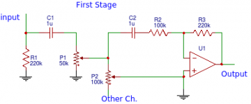
attached first stage scheme.
I was thinking to lowering The R2 & R3 to smaller value lika 47k & 100k respectively to decrease the noise. But isn't it will overload the pot?
Should I cut the trace between the balance pot and C2 then add a simple buffer (using JFET maybe 2sk30a) ? that way I can make the feedback resistor even lower value like 10k & 22k?
Moving the volume & balance pot to the end of 2nd stage is impossible, I mean I don't want to remake the PCB
Attachments
Hmmm... I don't think your going to get this to your liking tbh.
Reducing R2/R3 will help a bit but really these need to be reduced by a factor of 20 to really bring that stages noise contribution down. That said, 47k and the 50k pot should be OK (and even better if the pot is a linear one because R2 actually gives a near log law with a linear pot if you get the value right). Ideally C2 needs increasing, its marginal even now. Same for C1. That needs to be around 4.7uf if you want to preserve real LF information.
So no easy answer I'm afraid... its all compromise.
At least it worth to tryHmmm... I don't think your going to get this to your liking tbh.
I think the vol pot is quite log because it is in parallel with the ballance pot. Not an issue to meReducing R2/R3 will help a bit but really these need to be reduced by a factor of 20 to really bring that stages noise contribution down. That said, 47k and the 50k pot should be OK (and even better if the pot is a linear one because R2 actually gives a near log law with a linear pot if you get the value right). Ideally C2 needs increasing, its marginal even now. Same for C1. That needs to be around 4.7uf if you want to preserve real LF information.
So no easy answer I'm afraid... its all compromise.
Ah, yes, C2 is feed from the pot, that is quite high imp' source...

C1 is feed from walkman/android phone, I don't think this need to be too high value, my speaker can't handle very low freq' though
I also investigate that second stage (baxandal tone controll) add some noise when the bass/treble pot being boost. Bass & treble pot is 100k, I'm gona redesign this tone control with 50k pot to reduce some more noise.
thank you Mooly,

- Status
- This old topic is closed. If you want to reopen this topic, contact a moderator using the "Report Post" button.
- Home
- Source & Line
- Analog Line Level
- NE5532 Tone Control