Hi,
I built two of this and both are working fine with or without the display (Adafruit) and with or without using the LDO. After I solved my noise problem and doing some experimenting, I observed that it work if the supply is less than +-15 but with the +5V external (from a different supply). I was unable to "fire" it up if I use less than +-15 and internal +5V.
The specs says +-8.5V to +-18V. But I am not sure why on my two units, I have to use external 5V if my supply is less than 15. Hope you find the problem!
Thats interesting but I dont think it explains this?
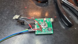
Only running the controller board now and the LDO circuit is fed with +14v (also tried +10v). Ideally I assume approx 6-7Vdc would be perfect for that purpose.
No display connected
Of course I can crank it up some but I cannot understand how that would improve things?
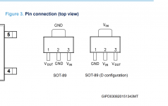
Only thing I can come up with is that Mouser sent me LDO with different pinout? (D-config)
This was what I ordered
https://no.mouser.com/ProductDetail...f//tDZEZckA==&countrycode=NO¤cycode=NOK
https://no.mouser.com/datasheet/2/389/ldk320-1374943.pdf
Not sure how I can check that yet, and could that cause this problem?
Only running the controller board now and the LDO circuit is fed with +14v (also tried +10v). Ideally I assume approx 6-7Vdc would be perfect for that purpose.
No display connected
Of course I can crank it up some but I cannot understand how that would improve things?
Only thing I can come up with is that Mouser sent me LDO with different pinout? (D-config)
This was what I ordered
https://no.mouser.com/ProductDetail...f//tDZEZckA==&countrycode=NO¤cycode=NOK
https://no.mouser.com/datasheet/2/389/ldk320-1374943.pdf
Not sure how I can check that yet, and could that cause this problem?
Attachments
Last edited:
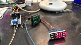
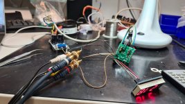

Ok it works fine.
Behold of the beautiful test setup here.
Great!! Nice to know you have sorted it out.
Let me try here: I am testing a board with the Muses72323. This has slightly different parameters for communication and I am not managing to get the board out of mute.
Basic question: I understand that in the initialization of the chip I need to send all the configuration parameter and then the volume control to set the resistors.
I assume I can forget about the gain part, as this is irrelevant.
Here is the test code I am using:
#include <SPI.h>
#include <LiquidCrystal_I2C.h>
LiquidCrystal_I2C lcd(0x27,20,4);
static const int s_slave_select_pin = 10;
static const SPISettings s_muses_spi_settings(250000, MSBFIRST, SPI_MODE2);
static const uint8_t s_control_attenuation_l = 0b00000000;
static const uint8_t s_control_attenuation_r = 0b00100000;
static const uint8_t s_control_gain_l = 0b00010000;
static const uint8_t s_control_gain_r = 0b00110000;
static const uint8_t s_control_states = 0b01000000;
void setup() {
uint16_t data1,vol_L,vol_R;
//Volume left
bitWrite(vol_L,0,false);
bitWrite(vol_L,1,false);
bitWrite(vol_L,2,false);
bitWrite(vol_L,3,false);
bitWrite(vol_L,4,false);
bitWrite(vol_L,5,false);
bitWrite(vol_L,6,true);
bitWrite(vol_L,7,false);
bitWrite(vol_L,8,false);
bitWrite(vol_L,9,false);
bitWrite(vol_L,10,false);
bitWrite(vol_L,11,false);
bitWrite(vol_L,12,true);
bitWrite(vol_L,13,false);
bitWrite(vol_L,14,false);
bitWrite(vol_L,15,false);
//Volume Right
bitWrite(vol_R,0,false);
bitWrite(vol_R,1,true);
bitWrite(vol_R,2,false);
bitWrite(vol_R,3,false);
bitWrite(vol_R,4,false);
bitWrite(vol_R,5,false);
bitWrite(vol_R,6,false);
bitWrite(vol_R,7,false);
bitWrite(vol_R,8,false);
bitWrite(vol_R,9,false);
bitWrite(vol_R,10,false);
bitWrite(vol_R,11,false);
bitWrite(vol_R,12,true);
bitWrite(vol_R,13,false);
bitWrite(vol_R,14,false);
bitWrite(vol_R,15,false);
//settigs
bitWrite(data1,0,false);
bitWrite(data1,1,false);
bitWrite(data1,2,true);
bitWrite(data1,3,true);
bitWrite(data1,4,false);
bitWrite(data1,5,false);
bitWrite(data1,6,false);
bitWrite(data1,7,false);
bitWrite(data1,8,false);
bitWrite(data1,9,true);
bitWrite(data1,10,false);
bitWrite(data1,11,false);
bitWrite(data1,12,false);
bitWrite(data1,13,false);
bitWrite(data1,14,false);
bitWrite(data1,15,false);
// put your setup code here, to run once:
lcd.init();
lcd.backlight();
lcd.clear();
//Initialize SPI
pinMode(s_slave_select_pin, OUTPUT);
SPI.begin();
SPI.setBitOrder(MSBFIRST);
SPI.setDataMode(SPI_MODE2);
// initialize SPI:
SPI.setClockDivider(SPI_CLOCK_DIV64);
digitalWrite(s_slave_select_pin, LOW);
SPI.transfer(data1);
digitalWrite(s_slave_select_pin, HIGH);
delay(100);
digitalWrite(s_slave_select_pin, LOW);
SPI.transfer(vol_R);
digitalWrite(s_slave_select_pin, HIGH);
delay(100);
digitalWrite(s_slave_select_pin, LOW);
SPI.transfer(vol_L);
digitalWrite(s_slave_select_pin, HIGH);
delay(100);
SPI.endTransaction();
lcd.print(vol_L);
}
void loop() {
// put your main code here, to run repeatedly:
}
What am I doing wrong ? I attached the documentation of the chip and the schematic of my board, that is inspired by Daniel advices. (Credit to him)
Regards,
Davide
Attachments
Hi,
it is not really clear what you are doing with your code.
Its like arduino code?
In my opinion: forget arduino
Bit0,1 = Chip address
Bit2,3 = Select address
They should even for all registers.
But you use different values for all transmit data.
Also it will be good to use unambiguous variable names.
Not only for volume l/r
Yes,
it is a test arduino code.
The way I understood it is bit 0 and 1 select the physical chip address, so in my case it is 00.
bit 2 and 3 select address:
00 Left Attenuation
01 Right Attenuation
10 Gain Setting
11 Options
So the chip start in mute.
I need to disable the soft-step and the zero crossing and tell him to use the internal clock.
So I first send:
0000001000001100
Then I set the volume for example to max (0db) sending:
0001000000000000
0001000000000100
And I should have the chip up and running at max volume.
I should not need to set anything on the gain setting.
The external clock is not connected (note this feature is not included in the Muses72320)
The chip keep staying in mute and I do not understand why.
Thanks,
Davide
Sorry, my mistake with the register select address
bitWrite(data1,0,false);
Does it means false value for bit 0 of data1?
In this case, you didn’t write the same value for all variables.
//Volume left
bitWrite(vol_L,0,false);
bitWrite(vol_L,1,false);
bitWrite(vol_L,2,false);
bitWrite(vol_L,3,false);
bitWrite(vol_L,4,false);
bitWrite(vol_L,5,false);
bitWrite(vol_L,6,true);
bitWrite(vol_L,7,false);
bitWrite(vol_L,8,false);
bitWrite(vol_L,9,false);
bitWrite(vol_L,10,false);
bitWrite(vol_L,11,false);
bitWrite(vol_L,12,true);
bitWrite(vol_L,13,false);
bitWrite(vol_L,14,false);
bitWrite(vol_L,15,false);
//Volume Right
bitWrite(vol_R,0,false);
bitWrite(vol_R,1,true);
bitWrite(vol_R,2,false);
bitWrite(vol_R,3,false);
bitWrite(vol_R,4,false);
bitWrite(vol_R,5,false);
bitWrite(vol_R,6,false);
bitWrite(vol_R,7,false);
bitWrite(vol_R,8,false);
bitWrite(vol_R,9,false);
bitWrite(vol_R,10,false);
bitWrite(vol_R,11,false);
bitWrite(vol_R,12,true);
bitWrite(vol_R,13,false);
bitWrite(vol_R,14,false);
bitWrite(vol_R,15,false);
//settigs
bitWrite(data1,0,false);
bitWrite(data1,1,false);
bitWrite(data1,2,true);
bitWrite(data1,3,true);
bitWrite(data1,4,false);
bitWrite(data1,5,false);
bitWrite(data1,6,false);
bitWrite(data1,7,false);
bitWrite(data1,8,false);
bitWrite(data1,9,true);
bitWrite(data1,10,false);
bitWrite(data1,11,false);
bitWrite(data1,12,false);
bitWrite(data1,13,false);
bitWrite(data1,14,false);
bitWrite(data1,15,false);
bitWrite(data1,0,false);
Does it means false value for bit 0 of data1?
In this case, you didn’t write the same value for all variables.
Last edited:
Sorry, my mistake with the register select address
bitWrite(data1,0,false);
Does it means false value for bit 0 of data1?
In this case, you didn’t write the same value for all variables.
Yes, bit Write does exactly that.
The value of the attenuation is not important, my problem is that it does not work at all, so I did not understand if I am doing something wrong with the schematic, with the clock_in pin or with the code.
Do you need to initialize it in any way ?
Is it correct that I can forget about the gain settings?
Regards,
Davide
Your values are not correct.
LSB is at the right of the table in the datasheet.
So bit0 and bit1 should be 0 for all registers if you connect the address pins to gnd.
In your case you can forget the gain settings.
I connected the clock pin to gnd and use the internal clock.
LSB is at the right of the table in the datasheet.
So bit0 and bit1 should be 0 for all registers if you connect the address pins to gnd.
In your case you can forget the gain settings.
I connected the clock pin to gnd and use the internal clock.
I am getting crazy about this thing:
I have three boards I am working on:
1) It has the regulators and the muses, no buffers: It never works.
2) One board only with the muses and the minimum to make it work: It works with my software
3) A full board: I get some signal through and some attenuation only in some ranges of steps and only on one channel.
I also tried to power the board with the muses that works(#2) through the regulators of boards #3 and it still works.
Either I am damaging/killing the Muses chips while soldering (but I used 250C no more) or I cannot explain it. All the chips on the three boards draw 2mA from the power supply, that is about right. I can see changes on the input signal when the chip goes on. So if #1 and #3 are damaged, are not 100% dead.
I noticed a mistake in my schematic. The capacitor on D_CAP goes to ground, not to -15V. It works like this on board #2, I tried to re-route it on board #3 but with no results.
I am really puzzled and don't know what to do. I have been trying to troubleshoot this for three days, with no definitive results.
Anything you might thing about to try ?
Thanks,
Davide
Last edited:
One question about power supply and audio quality:
I have the following situation. The main power of my pre-amp is +-24V filtered but unrequlated and a +5V (regulated) for the Arduino controller. The Muses board I made has regulators for +- 15V and +5V.
The question is the following: where do you think it is better to source the 5VRAW for the muses ?
1) From the +24V of the audio part.
2) From the 5V power supply for the Arduino.
With Option 1) I could use a optocoupler for the SPI and keep the ground of the Arduino away from the audio part, although the digital part of the Muses will be on it.
With Option 2) the 24V power supply will take care of all the audio and the 5V of all the control.
thanks,
Davide
Hi,
I have the 2019 Muse kit from Meladano, but unfornatully the alps pot I purchased is a 90° angled.
May someone give me the part number of the right pot for the little controller board please ?
I'm also looking for the reference of the 10 pins single raw femal high profile socket for the stacking...
Help much appreciated
- Home
- Source & Line
- Analog Line Level
- MUSES 72320 electronic volume