Sp-10 problems...
Hello hobbit, I have built a couple of these regulators in the past few yeas and they work very well. There are a couple mistakes on the schematics/parts list for the regulator and the preamp. Other than R9 the boards are marked correctly as I recall. First R9 in the power supply is not 3.3 ohm, it is 3.3 megohm. I used 2 meg which works fine. R9 along with C9 provide a slow turn on/ramp up of the B+. The HV regulator IC4 will not work unless you have 15 volts out of IC3 to power it. After you replace R9 check for 15 volts on one end of R8 and about 7 volts on the other end. For the filament supplies, if you used other than the specified transistor you have to watch the pinout. The 10k filament adjust trimmers are a bit sensitive so you may have to adjust them nearly to the end of their travel.I would leave the power supply outputs disconnected until you get the power supply working, then get the preamp board working next.
Good luck with your project, Dave
Last edited:
Hello hobbit, it looks like your filament capacitor C01 is installed backwards (unless my board is a different revision). Did you use the 2sa1015 small transistors as listed or did you use a substitute. J6 out has one side grounded to common, J7 out is 'floating' so it best to measure output across the J6 and J7 terminals and not to ground. You should have about 21 vdc across C01 and C02. Let me know if this helps. I can put a supply on my workbench and take some measurements if needed.... Dave
Hello hobbit, I checked the voltages in one of my supplies and the results are listed below. The KSA1015 has the correct pinout. There is not much here to go wrong If your voltages are way off then I would suspect the 317K or ksa1015 may be damaged.
I hope the attachment of the schematic comes through.... Dave
I hope the attachment of the schematic comes through.... Dave
Attachments
Hi Dave, thanks for your help, I reseated A1015 in its correct position and that I have the voltages at the output of the lm317 matching of j6 and j7 outputs must be damaged. I ordered some new lm317 motorola, when I hope to be working properly and the power to continue the project.
If you comment on the preamp board had some wrong component, I have already assembled and I would take this into account.
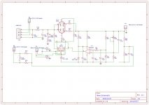
I enclose my psu schemes and preamp pcb.
A greeting Javier.
If you comment on the preamp board had some wrong component, I have already assembled and I would take this into account.
I enclose my psu schemes and preamp pcb.
A greeting Javier.
Attachments
LM317K...
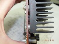
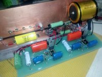
Hello hobbit, I am making notes on the power supply and preamp schematics and will send them on tomorrow. Regarding the LM317K I have attached a picture below showing how I mount mine. The heat-sinks should be held above the board with a common shouldered insulator like you used on the 317 screws. You can see how the leads 'wicked' the solder through the boards. If the lead holes on your heat-sinks are small they could short out. Also the heat-sinks should not be touching since the317's are at 120vdc difference in potential, this is just a good building practice...Dave
Hello hobbit, I am making notes on the power supply and preamp schematics and will send them on tomorrow. Regarding the LM317K I have attached a picture below showing how I mount mine. The heat-sinks should be held above the board with a common shouldered insulator like you used on the 317 screws. You can see how the leads 'wicked' the solder through the boards. If the lead holes on your heat-sinks are small they could short out. Also the heat-sinks should not be touching since the317's are at 120vdc difference in potential, this is just a good building practice...Dave
Attachments
Last edited:
Lm317 mounting...
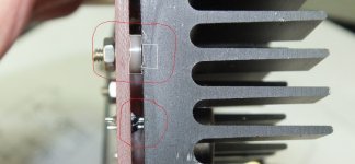
Hello hobbit, I looked more closely at the pictures you posted and it looks like you have insulators on the lm317 mounting screws. The insulators should be removed. The metal case of the lm317 is the output terminal. The screws conduct the output voltage from the 317 case to the circuit traces on the bottom of the circuit board. Use an insulator between the board and the heat-sink to prevent the heat-sink from shorting to the screws as shown below. A quick test is to measure ohms from the 317 case to the + output terminal block, you should have near 0 ohms...Dave
Hello hobbit, I looked more closely at the pictures you posted and it looks like you have insulators on the lm317 mounting screws. The insulators should be removed. The metal case of the lm317 is the output terminal. The screws conduct the output voltage from the 317 case to the circuit traces on the bottom of the circuit board. Use an insulator between the board and the heat-sink to prevent the heat-sink from shorting to the screws as shown below. A quick test is to measure ohms from the 317 case to the + output terminal block, you should have near 0 ohms...Dave
Attachments
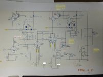
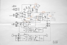
Hello hobbit, attached are the SP-10 schematics with updates and comments. Look over the schematics and if you have any question or comments let me know....Dave
I’ve been working on HV Jung Regulators and came up
With one that works well, and is similar to the SP-10 but with much
Better performance and output current. I’m using Vishay 2% 1.3W Zeners.
Attachments
Helli,
Here there sp10 clone :
Preamplificateur SP10 en DIY, est-ce possible? - Le forum Audiovintage
Here there sp10 clone :
Preamplificateur SP10 en DIY, est-ce possible? - Le forum Audiovintage
Hello,
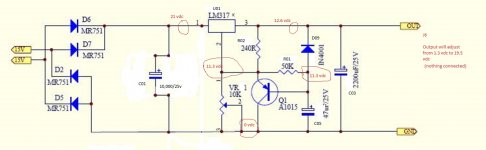
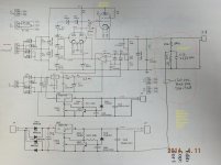
I come back to this ancient thread because I just assembled such a SP10 clone, and I'm facing a problem with high voltage. It's only 240V instead of 305V. I send an attachment with measured voltages, and what they should be between ().
All the components are new and I checked them carefully. The only difference is that I used 1N4750 diodes (as ARC did) instead of 1N4756 (as stated on the schematic and PCB).
The 1N4750 are 27V and the 1N4756 are 47V, it should explain the difference. But ARC used 1N4750 as written on the service manual, so I feel a bit confused about it.
Could someone explain what is the issue here ? Or is it just a typo on the ARC service manual ?
Thanks for your help.
Cyril.
Attachments
- Home
- Source & Line
- Analog Line Level
- Audio Research SP-10 Clone HELP please