copyright does NOT protect ideas, prevent their being shared, discussed
anyone is always free to post their own redrawing of the schematic
again copyright only protects an exact copy of the artwork or "artisitic expression"
not the intellectual content, the idea, which in a circuit is the topology, and even parts types, values
anyone is always free to post their own redrawing of the schematic
again copyright only protects an exact copy of the artwork or "artisitic expression"
not the intellectual content, the idea, which in a circuit is the topology, and even parts types, values
Exactly. Thank you for bringing in a bit of actual legal clarity into this.anyone is always free to post their own redrawing of the schematic
again copyright only protects an exact copy of the artwork or "artisitic expression"
not the intellectual content, the idea, which in a circuit is the topology, and even parts types, values
The copyright prevents someone from, say, distributing a photocopy of the schematic. It does not prevent anyone from redrawing the schematic using, say, different component shapes and numbers, and distributing that.
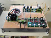
I finally found the time and money to get started on my build of this preamp. I have all boards populated with the exception of the Phono and LLLL boards. I fabricated some temporary interconnect cables and mounted the boards on a piece of plywood for testing. I did some quick bench test and this preamp appears to be working very nicely within specification. I will do some more detailed testing later. I was anxious to hear it so I hooked it up to my shop system. I like it. Like everyone else has noted it is dead quiet. Next month I will tackle the Phono and LLLL boards. I will probably DIY a wood case. Enclosures are a bit pricy.
I noticed a few issues that I believe are non-issues after referring to Mr. Self's books.
One: Overall gain. The magazine article states a maximum of +16dB. I measured +10dB. Then I realized I was using the unbalanced outputs to my bench meter. If I measure the AC voltage across hot and cold I get +16dB. I have never used balanced inputs and outputs before.
Two: I cannot achieve a complete null with the volume pot at minimum. I can still hear the faint sound of the music. In his book "Small Signal Audio Design" he indicates that the noise output of a Baxandall volume control is not zero when the volume is set to minimum. I assume this also applies to a signal source feeding through as well.
Three: Overall gain again. This is a hot preamp. I am sure I have read other builders comments on this. I can barely get the volume pot off of minimum to achieve my normal listening level. If the wife is gone I can go as high as the 9am position. But never higher than this. Ideally, I would like to be somewhere around midpoint for my normal listening pleasure.
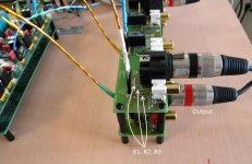
Can someone with the article or schematic look at the Input/output board and tell me what R1, R2, and R3 are for? The BOM calls for a 0R value. I suspect that adding resistance here can be used to attenuate or pad the output.
I noticed a few issues that I believe are non-issues after referring to Mr. Self's books.
One: Overall gain. The magazine article states a maximum of +16dB. I measured +10dB. Then I realized I was using the unbalanced outputs to my bench meter. If I measure the AC voltage across hot and cold I get +16dB. I have never used balanced inputs and outputs before.
Two: I cannot achieve a complete null with the volume pot at minimum. I can still hear the faint sound of the music. In his book "Small Signal Audio Design" he indicates that the noise output of a Baxandall volume control is not zero when the volume is set to minimum. I assume this also applies to a signal source feeding through as well.
Three: Overall gain again. This is a hot preamp. I am sure I have read other builders comments on this. I can barely get the volume pot off of minimum to achieve my normal listening level. If the wife is gone I can go as high as the 9am position. But never higher than this. Ideally, I would like to be somewhere around midpoint for my normal listening pleasure.
Can someone with the article or schematic look at the Input/output board and tell me what R1, R2, and R3 are for? The BOM calls for a 0R value. I suspect that adding resistance here can be used to attenuate or pad the output.
Attachments
+16dB (across both poles) is a gain of 6.3times.
If you put in a following receiver impedance of 10k (5k on each pole), then you can attenuate the signal by inserting a 2572r reistor in series with each line out and then a 510r shunting the two lines to audio ground.
If this gives a better control of speaker volumes, then you need to find a way to reduce your amplifier gain and/or your preamplifier gain by that excess +16dB.
The 2572r and 510 r in each half of the balnced impedance line means the preamp is driving a 5k24 load impedance. I presume it will do that comfortably.
Put the temporary attenuator at the receiver end.
Last edited:
+16dB (across both poles) is a gain of 6.3times.
If you put in a following receiver impedance of 10k (5k on each pole), then you can attenuate the signal by inserting a 2572r reistor in series with each line out and then a 510r shunting the two lines to audio ground.
If this gives a better control of speaker volumes, then you need to find a way to reduce your amplifier gain and/or your preamplifier gain by that excess +16dB.
The 2572r and 510 r in each half of the balnced impedance line means the preamp is driving a 5k24 load impedance. I presume it will do that comfortably.
Put the temporary attenuator at the receiver end.
Andrew I would argue NOT to put two resistors to ground, but to put three resistors in series between the poles, like 10k - 5144 - 10k (probably changed values).
Keep away from ground, can only decrease signal cleanliness.
Jan
audio ground, not chassis.Andrew I would argue NOT to put two resistors to ground, but to put three resistors in series between the poles, like 10k - 5144 - 10k (probably changed values).
Keep away from ground, can only decrease signal cleanliness.
Jan
Dirk, I can guarantee just about every piece of music you have ever listened to has passed though a dozen or more 5532s. They are very, very common in even high end recording kit.
I have some schematics from famous audio mixers used world wide in sound studios. Full of 55xx op amps.
audio ground, not chassis.
´Audio ground´ is an oxymoron.
I Two: I cannot achieve a complete null with the volume pot at minimum. I can still hear the faint sound of the music. In his book "Small Signal Audio Design" he indicates that the noise output of a Baxandall volume control is not zero when the volume is set to minimum. I assume this also applies to a signal source feeding through as well.
Although the noise contribution is ever present, the signal should reduce to zero in amplitude. If it is not doing so then the most obvious suspect has to be the pots. You can prove that in seconds by linking the centre wiper terminal of each gang to the appropriate end terminals of the pot. Even an ohm or two of residual resistance is enough to cause detectable audio.
You can prove that in seconds by linking the centre wiper terminal of each gang to the appropriate end terminals of the pot.
Thanks Mooly for the troubleshooting tip. No change. Let me clarify that at minimum volume I hear only a very faint audio.
This is not in a metal case and open to the room. Could this be the problem? Or maybe an open ground in my cabling? I will check that tonight.
Other than this and a hot output this preamp sounds and measures nicely.
@Andrew: I am still studying (reading Self's books) on this problem and how adding the resistors in series will effect the output impedance. I may experiment tonight. This is my first build and really is an exercise in learning.
the ladder in it's simplest version can be seen as two resistors. One in series with the line and one shunting to the audio ground.
The input sees the line resistor and that is followed by the shunting resistor in parallel with the Rin/Zin of the Receiver. for the values I gacve of 2572 and 510 in parallel with 5k
The parallel combination comes out at 510*5000/(510+5000) = 462r8 and when added to the series gives a Rin presented to the source of 3034r8
Since you have a Balanced impedance connection the source sees the two halves coming to a total of 6069.6ohms
The output impedance of the attenuator looking back from the Receiver is the 510r shunting resistor to audio ground followed by the 2572r in series with the source impednace. I'll guess at 100ohms.
The Receiver sees 510//{100ohms+2572) = 510*2672/(510+2672) =428.3ohms.
The receiver sees a higher impedance. It has gone up from 100ohms to 430ohms. Suits short and medium cables, rather than all cables.
The modified version suggested by Jan.D omits the audio ground and combines the two 510r
This then comes to a three resistor ladder: 2k7 + 1k + 2k7 for a total of 6400r.
The 1k is in parallel with the 10k input and the source sees 2k7+2k7 + (1k||10k) = 6k3091
Virtually the same of the two sets of two resistor ladders.
TheReceiver sees the 1k in parallel with the 2k7+2k7+100+100 = 1k||5k6 = 848ohms
Virtually the same as the previous 2*430ohms
This attenuation is 1000/(1000+2700+2700+100+100) = 1000/6600 = -16.4dB
using standard E12 resistors. BUT!!!!! you must match them to a lot better than +-1% try for <0.05%
Thanks Mooly for the troubleshooting tip. No change. Let me clarify that at minimum volume I hear only a very faint audio.
This is not in a metal case and open to the room. Could this be the problem? Or maybe an open ground in my cabling? I will check that tonight.
The active volume control should certainly give zero output under those conditions (wiper shorted giving 100% negative feedback). I suppose a valid question is whether anyone else has observed this behaviour or not.
To fault find this issue further requires some careful testing. Two possible causes could be:
a/ capacitive coupling of the signal somewhere in the signal change. That is pretty much totally layout dependent and given the low impedances involved generally seems unlikely. A clue to capacitive coupling is that the audio would be 'tinny' having mainly HF content.
b/ Some mistake in the physical wiring somewhere.
If you look at the circuit and locate the 10 ohm summing resistors (R29-32 and R67-70) then you could try adding a shorting link from the junction of those resistors to pins 3 and pins 5 respectively of IC9 and IC18 then that will 100% short audio to the correct audio ground and should fully remove the signal. If it doesn't then the breakthrough is occurring after that point.
It is almost impossible to get really zero sifnal with the level all the way down. There is always some residual R somewhere. Even when you short it as Mooly suggested, there is still residual resistance in wiring, the shorting wire clips, etc.
Don't forget that our hearing is logaritmic and very sensitive, even a residual signal of say 100uV from 1V, being 'only' -80dB, is enough to be heard.
I believe you are chasing a non-problem.
Jan
Don't forget that our hearing is logaritmic and very sensitive, even a residual signal of say 100uV from 1V, being 'only' -80dB, is enough to be heard.
I believe you are chasing a non-problem.
Jan
You can hear something with a 10k pot in zero position, but you can't with 50k pot.
You mean 'you' as in 'in my case, with two different pots'?
Jan
The active volume control should certainly give zero output under those conditions (wiper shorted giving 100% negative feedback). I suppose a valid question is whether anyone else has observed this behaviour or not.
To fault find this issue further requires some careful testing. Two possible causes could be:
a/ capacitive coupling of the signal somewhere in the signal change. That is pretty much totally layout dependent and given the low impedances involved generally seems unlikely. A clue to capacitive coupling is that the audio would be 'tinny' having mainly HF content.
b/ Some mistake in the physical wiring somewhere.
If you look at the circuit and locate the 10 ohm summing resistors (R29-32 and R67-70) then you could try adding a shorting link from the junction of those resistors to pins 3 and pins 5 respectively of IC9 and IC18 then that will 100% short audio to the correct audio ground and should fully remove the signal. If it doesn't then the breakthrough is occurring after that point.
With the Baxandall volume control, it is important to not overlook the imperfections of the op amp when looking for zero output. The issue is closed-loop output impedance. If you connect an op amp as a unity-gain buffer and connect its positive input to ground, the output should be at zero with an output impedance equal to its closed-loop unity gain output impedance. This impedance is finite. Now drive signal into the output through a resistor of, say 10k. A signal will appear at the output that has been divided down by the ratio of 10k to the closed loop output impedance of the buffer. This circuit is the exact circuit of when the Baxandall volume control is set to zero.
Suppose the closed loop output impedance of the buffer so formed is 10 ohms and that we drive 1V into the 10k resistor. Attenuation of this arrangement is only a mere 60dB.
So how low do we really think the closed loop output impedance really is, and at what frequency? This depends on the open loop output impedance of the op amp and the amount of feedback at the given frequency. Here is where we must get very speculative. We also note that if the op amp has any crossover distortion, its open loop output impedance will be changing as the applied signal current moves the output stage through the crossover region, while will cause the tiny residual signal to be distorted.
We might have 80dB of feedback at 1kHz if the op amp gain-bandwidth is 10MHz and it is conventionally compensated. Suppose its open loop output impedance is as high as 1k at 1kHz (I'm guessing this is pretty high). The closed loop output impedance of the buffer might then be on the order of 0.1 ohm, which is 100 times less that the 10 ohm closed loop output impedance I used as an example above. We would now have a theoretical attenuation of 80dB, which is much better, but still finite.
The whole effect can be evaluated by measurement in much the same way we measure the damping factor of a power amplifier. We take the same op amp used in the preamp (5532) and connect it as a unity-gain buffer in a test circuit, then back-drive its output with 1V through a 10k resistor.
Cheers,
Bob
The active volume control should certainly give zero output under those conditions (wiper shorted giving 100% negative feedback). I suppose a valid question is whether anyone else has observed this behaviour or not..
I was wondering this myself. Hopefully someone who has built this preamp will chime in.
If you look at the circuit and locate the 10 ohm summing resistors (R29-32 and R67-70) then you could try adding a shorting link from the junction of those resistors to pins 3 and pins 5 respectively of IC9 and IC18 then that will 100% short audio to the correct audio ground and should fully remove the signal. If it doesn't then the breakthrough is occurring after that point.
This is how I did the test yesterday. Much easier to access these test points than the equivalent test points on the pot.
With the Baxandall volume control, it is important to not overlook the imperfections of the op amp when looking for zero output. The issue is closed-loop output impedance. If you connect an op amp as a unity-gain buffer and connect its positive input to ground, the output should be at zero with an output impedance equal to its closed-loop unity gain output impedance. This impedance is finite. Cheers,
Bob
Thanks for the detailed explanation Bob. I remember the debate on whether crossover distortion of the opamp became significant at high attenuation with this kind of circuit...
I've just had a look back over the 'Active Volume Control for Professional Audio' published by TI which is essentially Dougs original implementation of an active volume control. TI quote a measured 'off' gain of -103db using an OPA1602 opamp.
What I have overlooked completely is that the later 2012 preamp in its pursuit of low impedance/low noise design sums four opamps via 10 ohm resistors and that the combined effect of these resistors (2.5 ohms) is added to the output impedance of the stage. This does indeed give an 'off' attenuation of just -65db and so yes, there will be noticeable audio.
I was wondering this myself. Hopefully someone who has built this preamp will chime in.
Looking in depth at the circuit and it seems its an unavoidable consequence of the design.
Attachments
Thanks Mooly and Jan. This is not an issue for me to worry about. Just something I notice different from other preamps I have used.
It looks like I have a successful build first time around.
Doug Self talks about the advantages of a combination active/passive volume control where the passive side is at ground when the control is minimum. Something for me to consider should I ever decide to roll my own. Not anytime soon.
Now to solve the hot output issue. Andrew has provided a lot for me to digest.
- Home
- Source & Line
- Analog Line Level
- New Doug Self pre-amp design...