Remotely Controlled Motorized Volume Pot. + Free Software
Of course, there are a lot of similar projects on the market that offered either like pre assembled units or like kits. Here the difference is that the HEX code to program your own PIC16F88 is FREE!
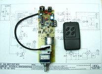
The unit is remotely controlled with the use of RC-5 protocol. A brief description of unit: It offers the VOL+ and VOL- functions plus STBY and MUTE.
The micro is programmed to communicate with any RC5 compatible remote control handset. Each handset transmits a unique address code, e.g. TV address = 0 and Preamplifier address = 16. To initialize the micro for communication with a remote handset, we have to turn off the supply of micro and then to turn it on again. Then immediately the red LED starts to blink fast 10 times. Within this time we have to press firmly the button mounted on PCB until LED stops to blink and remains constantly glowing and then we release the button. Now, and within 3 seconds we have to press firmly a button (MUTE is preferred) on remote control. If address has been stored successfully, then the LED blinks slowly 6 times and we can release the button. If we don’t press any button on remote control then the TV address code = 0 is automatically stored in micro and the LED does not lit. If the remote control is incompatible with RC-5, then the LED starts to blink fast for 10 times and in micro is again stored the TV address = 0. That is all. The internal EEPROM of micro retains constantly the address code that stored.
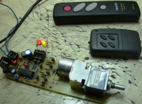
In the picture you can see that I have connected the IR receiver with a screened cable of 20cm to the PCB. This not cause interference or missed signal problems and, at the same time, offers flexibility in the mounting of IR receiver IC on front panel of device.
For more details, schematics, PCB drawings and... of course to download the free HEX file (with it you can use any programmer able to program a PIC16F88) please here:
Matrix Multimedia user forums • View topic - Remotely Controlled Motorized Volume Pot.
Of course, there are a lot of similar projects on the market that offered either like pre assembled units or like kits. Here the difference is that the HEX code to program your own PIC16F88 is FREE!
The unit is remotely controlled with the use of RC-5 protocol. A brief description of unit: It offers the VOL+ and VOL- functions plus STBY and MUTE.
The micro is programmed to communicate with any RC5 compatible remote control handset. Each handset transmits a unique address code, e.g. TV address = 0 and Preamplifier address = 16. To initialize the micro for communication with a remote handset, we have to turn off the supply of micro and then to turn it on again. Then immediately the red LED starts to blink fast 10 times. Within this time we have to press firmly the button mounted on PCB until LED stops to blink and remains constantly glowing and then we release the button. Now, and within 3 seconds we have to press firmly a button (MUTE is preferred) on remote control. If address has been stored successfully, then the LED blinks slowly 6 times and we can release the button. If we don’t press any button on remote control then the TV address code = 0 is automatically stored in micro and the LED does not lit. If the remote control is incompatible with RC-5, then the LED starts to blink fast for 10 times and in micro is again stored the TV address = 0. That is all. The internal EEPROM of micro retains constantly the address code that stored.
In the picture you can see that I have connected the IR receiver with a screened cable of 20cm to the PCB. This not cause interference or missed signal problems and, at the same time, offers flexibility in the mounting of IR receiver IC on front panel of device.
For more details, schematics, PCB drawings and... of course to download the free HEX file (with it you can use any programmer able to program a PIC16F88) please here:
Matrix Multimedia user forums • View topic - Remotely Controlled Motorized Volume Pot.
Attachments
Last edited:
Hi fotios,
nice project.
Could you tell me how you managed the behaviour of the pot for single push/constant push oh the remote control ?
Thanks,
Max
Thank you Max
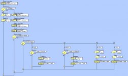
I hope you know some things about RC-5 transmition protocol. The process is based on the examination "If Toggle Bit flips state". When a button on remote control is firmly pressed the "Toggle Bit" does not change state, while if button released it does. In program code and for VOL+ and VOL- functions, the test "If Toggle Bit flips state" is omitted and a time delay of 100ms in the specific program loops prevents empty intervals between succesive train of pulses. So, as long as VOL+ or VOL- buttons on remote control are firmly pressed, the potentiometer is rotated continuously. When button is released the rotation stoped.
On the contrary, for STBY and MUTE functions "If Toggle Bit changes state" is taken into account in program code. So if e.g. the STBY button is firmly pressed, the receiver does not change continuously state. We have to release and to press again the button to do so.
Hope i was somehow understandable.
Last edited:
Max, here is a FlowChart that might help you understand better?Hi fotios,
nice project.
Could you tell me how you managed the behaviour of the pot for single push/constant push oh the remote control ?
Thanks,
Max
Attachments
PCBs and microcontroller
Though i offered the program code free as a gift to diyAudio members instead a money donation to forum (is the same thing) some people asked me for availability of PCBs and pre-programmed micros. Most of them are users of "Lightspeed attenuator". For this use, there is no need for an expensive ALPS Blue Velvet motorized pot (23 Euro the lowest price on e-bay) or for the RK16 series (16 Euro). Recently, the well known for its quality BOURNS launched a range of economic motorized potentiometers for audio use. Mouser has stocked some values (10K, 50K) of these potentiometers for 9,50 Euro/piece. I allready ordered two pieces to try them. So, i will draw a second PCB with the footprint of BOURNS.
I think BOURNS will make the job pretty good.
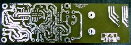
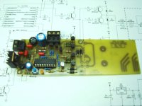
Well, I can offer you pcbs and micros in the less possible expense. To this, pcbs will be simply tinned - no solder mask, no silkscreen - for saving cost, like this on the first picture.
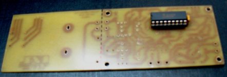
1) A simple PCB with the programmed micro mounted on it:
18 Euro + 4,5 Euro p&p (registered parcel) + 1 Euro PayPal fees = 23.5 Euro (see picture 2)
2) Ready assembled PCB (see picture 3):
30 Euro + 6 Euro p&p (registered parcel) + 1.6 Euro PayPal fees = 37.5 Euro
It should be noted that the PCB can be divided in two parts with the use of a blade. The one part is for the potentiometer while the other for the control circuit.
For any question or help, please don't hesitate to contact directly with me in the e-mail address shown bellow in my signature.
P.S. Please Mr. moderator, don't move the post in Swap-Meet forum.
Though i offered the program code free as a gift to diyAudio members instead a money donation to forum (is the same thing) some people asked me for availability of PCBs and pre-programmed micros. Most of them are users of "Lightspeed attenuator". For this use, there is no need for an expensive ALPS Blue Velvet motorized pot (23 Euro the lowest price on e-bay) or for the RK16 series (16 Euro). Recently, the well known for its quality BOURNS launched a range of economic motorized potentiometers for audio use. Mouser has stocked some values (10K, 50K) of these potentiometers for 9,50 Euro/piece. I allready ordered two pieces to try them. So, i will draw a second PCB with the footprint of BOURNS.
I think BOURNS will make the job pretty good.
Well, I can offer you pcbs and micros in the less possible expense. To this, pcbs will be simply tinned - no solder mask, no silkscreen - for saving cost, like this on the first picture.
1) A simple PCB with the programmed micro mounted on it:
18 Euro + 4,5 Euro p&p (registered parcel) + 1 Euro PayPal fees = 23.5 Euro (see picture 2)
2) Ready assembled PCB (see picture 3):
30 Euro + 6 Euro p&p (registered parcel) + 1.6 Euro PayPal fees = 37.5 Euro
It should be noted that the PCB can be divided in two parts with the use of a blade. The one part is for the potentiometer while the other for the control circuit.
For any question or help, please don't hesitate to contact directly with me in the e-mail address shown bellow in my signature.
P.S. Please Mr. moderator, don't move the post in Swap-Meet forum.
Attachments
REMOTE CONTROL HANDSET
A remote control handset with just 4 functions (i.e. 4 buttons for VOL+, VOL-, STBY, MUTE) as many as supports the microcontroller in the current project will be available very soon. The program code is ready and tested with success on actual hardware. Simply i am on the search to find a suitable ABS handheld case in the lowest possible price. I don't want the price of the final device to be more than 7 to 8 Euro.
In this way i will save myself and other people from those universal remote controls cluttered from 30 to 50 useless buttons. Another one benefit of this custom handset will be its transmition address = 16 or 19 which are the RC-5 protocol predefined addresses for preamplifiers. So, no messing with TV sets, CD-Players and vice-versa.
To the present i have located 3 - 4 good plastic cases in small dimensions. This in the first photo is a TEKO that costs arround 4 Euro. It is nice, but to obtain a better price i should place an order of 200 pieces at least.
A remote control handset with just 4 functions (i.e. 4 buttons for VOL+, VOL-, STBY, MUTE) as many as supports the microcontroller in the current project will be available very soon. The program code is ready and tested with success on actual hardware. Simply i am on the search to find a suitable ABS handheld case in the lowest possible price. I don't want the price of the final device to be more than 7 to 8 Euro.
In this way i will save myself and other people from those universal remote controls cluttered from 30 to 50 useless buttons. Another one benefit of this custom handset will be its transmition address = 16 or 19 which are the RC-5 protocol predefined addresses for preamplifiers. So, no messing with TV sets, CD-Players and vice-versa.
To the present i have located 3 - 4 good plastic cases in small dimensions. This in the first photo is a TEKO that costs arround 4 Euro. It is nice, but to obtain a better price i should place an order of 200 pieces
at least.Wow, great work man. Very nice of you to free the knowledge and source.
I have a old JDM Programmer and a spare PIC16F84 lying around from a old infrared project.
Can I use the PIC16F84 instead of the PIC16F88 with your plans?
Time to go to the basement and get my etchant, toner-transfer paper and copper boards.
Cheers,
deChrLAm
I have a old JDM Programmer and a spare PIC16F84 lying around from a old infrared project.
Can I use the PIC16F84 instead of the PIC16F88 with your plans?
Time to go to the basement and get my etchant, toner-transfer paper and copper boards.
Cheers,
deChrLAm
Wow, great work man. Very nice of you to free the knowledge and source.
I have a old JDM Programmer and a spare PIC16F84 lying around from a old infrared project.
Can I use the PIC16F84 instead of the PIC16F88 with your plans?
Time to go to the basement and get my etchant, toner-transfer paper and copper boards.
Cheers,
deChrLAm
Thanks for your kind words
Unfortunatelly P16F84 does not includes internal oscillator block. P16F88 includes INTOSC block and i use it. It is callibrated at 8MHz. I suggest you to buy a P16F88, is not so difficult to find it and is cheap. Otherwise - in the case you insist in the use of P16F84 - except code changes you should make and changes on PCB layout because you have to add an external XTAL of 8MHz and the associated caps (2 X 15-33pF).
For me, is not so difficult to change in program code the mcu and its configuration settings, but i haven't a P16F84
to test the changed code on actual hardware.Please let me know.
Thanks for checking fotios. I realised today when i saw no crystal on the board that some hardware changes would be needed. I was about to update the thread wih my conclusin. The newer pic chip is half the price i paid many years ago.
I will start etching the board this weekend and order my parts. I will also post some pics when it is finished. I also will probably remove or omit the mute and power functions.
I will start etching the board this weekend and order my parts. I will also post some pics when it is finished. I also will probably remove or omit the mute and power functions.
Thanks for checking fotios. I realised today when i saw no crystal on the board that some hardware changes would be needed. I was about to update the thread wih my conclusin. The newer pic chip is half the price i paid many years ago.
I will start etching the board this weekend and order my parts. I will also post some pics when it is finished. I also will probably remove or omit the mute and power functions.
Please keep MUTE switch on PCB. It is useful to establish communication between mcu and remote control handset. Take a look on instructions where this function is described.
Very nice alternative for P16F88 is the new P16F1827. Excellent micro with lot of new posibilities. I have some samples of it and i will do an upgrade of program code for this. I also have in process a mini remote control handset (like this in the picture) that uses the P16F1827. I will finish it in 2-3 days. P16F88 and P16F1827 are pin to pin compatible, so no changes on PCB layout.
@fotios, thanks for the tip about the mute switch.
What kind of capacitors are:
C1, C4, C6 100nF
C2 10nF
C7 220nF
In the picture C1 is different to C4 and C6 despite them all having the same value of 100nF
C1 is the supply decoupling capacitor of MCU and so it is the usual multilayer ceramic cap = 100nF.
C3 is electrolytic, if your AC input is greater than 12Vac please use a 470μF/35V. It has same dimensions and footprint like a 1000μF/16V.
All other capacitors are MKT type.
BTW, parts marked as LK (LK1,2,3,4,5,6,7) are just wire links.
Hi Fotios,
One more question. I am selecting a transformer for the board and my volume control. The volume control needs a maximum of 70 mA.
I was thinking 230VAC primary, single 6VAC secondary @ 3.2VA 534mA.
My mains voltage is a very steady 230VAC
Is this size OK?
Cheers,
deChrLam
One more question. I am selecting a transformer for the board and my volume control. The volume control needs a maximum of 70 mA.
I was thinking 230VAC primary, single 6VAC secondary @ 3.2VA 534mA.
My mains voltage is a very steady 230VAC
Is this size OK?
Cheers,
deChrLam
Hi Fotios,
One more question. I am selecting a transformer for the board and my volume control. The volume control needs a maximum of 70 mA.
I was thinking 230VAC primary, single 6VAC secondary @ 3.2VA 534mA.
My mains voltage is a very steady 230VAC
Is this size OK?
Cheers,
deChrLam
Yes, a 6VAC/534mA transformer is just fine. I use the same size.
Go ahead!
I wish you success.
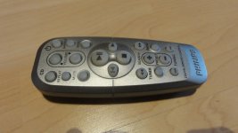
I got a remote control Philips RC 19420002-01 on yaBe for 1 Euro and it works just great. This remote has a different header to the TV codes and as expected does not interfere with my Philips TV.
This project was fun and painful at the same time. Next time around I think I will just buy the boards from fotios. The price is good and the concept is solid and professional.
Next step for me is to get the mute working with my existing soft start and speaker protection modules from here: AudioCreativ - High-End Kombimodul: Lautsprecherschutzschaltung + Softstart
I have a circuit diagram from the designer, but I cannot publish it here.
All the best
Attachments
Nice Achievement.
However I have that Same Alps pot w bigger motor though and a slightly more sophisticated Setup OEM on My Main amp, Selector switches are motorized as well
Frankly I don't use it. Because it's just.. another... stupid remote to deal with.
All for the sake of not getting up out of one's Chair ??
However I have that Same Alps pot w bigger motor though and a slightly more sophisticated Setup OEM on My Main amp, Selector switches are motorized as well
Frankly I don't use it. Because it's just.. another... stupid remote to deal with.
All for the sake of not getting up out of one's Chair ??
This is a wonderful idea! You can sit in your arm chair keeping hug your belovedBring the Pre-Amp to the listening seat.
Then full analogue control of all the signals sent to the Power Amplifiers/s
 preamplifier!
- Status
- This old topic is closed. If you want to reopen this topic, contact a moderator using the "Report Post" button.
- Home
- Source & Line
- Analog Line Level
- Remotely Controlled Motorized Volume Pot.