More juicy sauce for ya all!
As per my friend's results
"All simulations were run with IRF610/9610, 5.7x gain and 10K ohm load.
Note that real-world performance will never be as good as the simulation, but my experience with this is that it's a good approximation of reality.
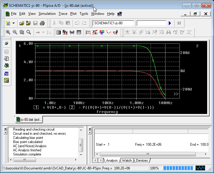
Amplitude (green) and phase (red) response. This is with a 1V input sweep from 0.1Hz to 100MHz. Note the output amplitude response is flat at 5.7V output (signifying the gain of 5.7) and begins to fall at >1MHz. It reaches the -3dB point (0.707x) at around 15MHz. The phase response is flat until after 100KHz where it gradually starts to deviate from 0 degree.
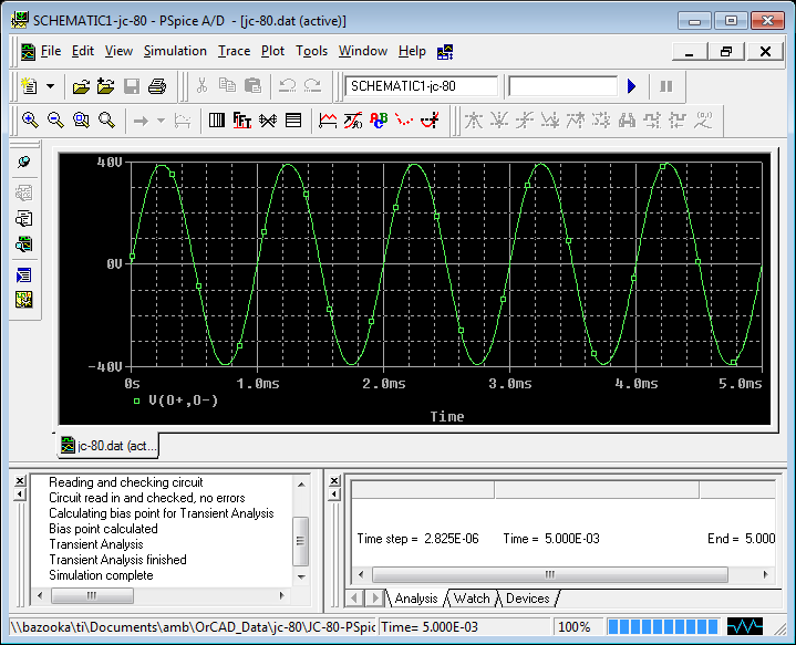
This is the amp swinging almost 80Vpp (28Vrms) 1KHz sine wave.
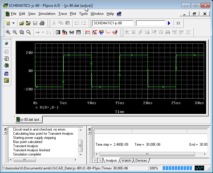
This is the amp swinging about 34Vpp 100KHz square wave.

Same as above, but with X axis expanded to show the square wave rising edge with greater resolution. The edge rises smoothly and produced only a very mild overshoot.
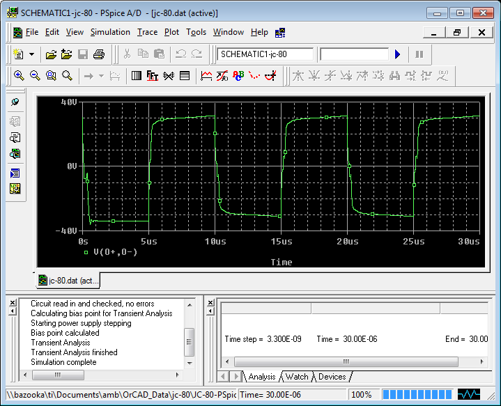
This is the amp swinging about 60Vpp 100KHz square wave. Something weird happens here, as the rising and falling edges become much slower and rounded. This shouldn't be an issue in actual use, as this circuit will never be swinging this much voltage when driving a power amp. The power amp would have gone into severe clipping at a much lower level.
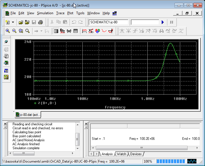
This is the output impedance of the amp. It's a constant 196 ohms (mostly contributed by the two 100 ohm output resistors), up until over 1MHz where it starts to rise, reaching a peak of about 238 ohms and then falling again beyond that.
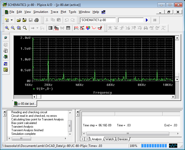
Harmonic distortion spectrum with a 1KHz sine wave fundamental, at 5.7V output. Note that the 2nd harmonic is 1.208uV in amplitude which makes it 0.000021%. There are no other significant even harmonics present, only odd harmonics, at 3KHz, 5KHz, 7KHz, 9KHz, etc. All those are even lower than the 2nd harmonic. The numbers look amazing, but this is one where real life
is probably much worse, because devices won't be as perfectly matched. Nevertheless these are excellent results."
Enjoy!
Do
As per my friend's results
"All simulations were run with IRF610/9610, 5.7x gain and 10K ohm load.
Note that real-world performance will never be as good as the simulation, but my experience with this is that it's a good approximation of reality.
Amplitude (green) and phase (red) response. This is with a 1V input sweep from 0.1Hz to 100MHz. Note the output amplitude response is flat at 5.7V output (signifying the gain of 5.7) and begins to fall at >1MHz. It reaches the -3dB point (0.707x) at around 15MHz. The phase response is flat until after 100KHz where it gradually starts to deviate from 0 degree.
This is the amp swinging almost 80Vpp (28Vrms) 1KHz sine wave.
This is the amp swinging about 34Vpp 100KHz square wave.
Same as above, but with X axis expanded to show the square wave rising edge with greater resolution. The edge rises smoothly and produced only a very mild overshoot.
This is the amp swinging about 60Vpp 100KHz square wave. Something weird happens here, as the rising and falling edges become much slower and rounded. This shouldn't be an issue in actual use, as this circuit will never be swinging this much voltage when driving a power amp. The power amp would have gone into severe clipping at a much lower level.
This is the output impedance of the amp. It's a constant 196 ohms (mostly contributed by the two 100 ohm output resistors), up until over 1MHz where it starts to rise, reaching a peak of about 238 ohms and then falling again beyond that.
Harmonic distortion spectrum with a 1KHz sine wave fundamental, at 5.7V output. Note that the 2nd harmonic is 1.208uV in amplitude which makes it 0.000021%. There are no other significant even harmonics present, only odd harmonics, at 3KHz, 5KHz, 7KHz, 9KHz, etc. All those are even lower than the 2nd harmonic. The numbers look amazing, but this is one where real life
is probably much worse, because devices won't be as perfectly matched. Nevertheless these are excellent results."
Enjoy!
Do
Yesssssss
But I plan to drive headphones so no problem?
If I had a copy of that model I would use it for sensitivity analysis. From day one most of my questions have surrounded the issue of matching. How close is close enough!
swinging about 60Vpp 100KHz square wave. Something weird happens here, as the rising and falling edges become much slower and rounded. This shouldn't be an issue in actual use . . . when driving a power amp.
But I plan to drive headphones so no problem?
If I had a copy of that model I would use it for sensitivity analysis. From day one most of my questions have surrounded the issue of matching. How close is close enough!
But I plan to drive headphones so no problem?
If I had a copy of that model I would use it for sensitivity analysis. From day one most of my questions have surrounded the issue of matching. How close is close enough!
BTW, this was by feeding it directly 24Vdc, bypassing the 30Vdc to 24Vdc regulator.
According to my friend, with a really good reg, you can safely bypass this regulator but not the 15V for the opamp...
The model is ran through PSpice on Orcad. Do you have the software? If yes, I can ask him again.
Ciao!
Do
Yes, & Yessssssssss
Yes, and please do.
I would create component models for each of the active components typically matched (jfets, and mosfets), by first cloning and renaming the matched part, running again to assure no errors and then altering the values on which matching is usually performed. We know higher IDSS is better but is 3% match good enough?
The combination of this and socketed actives would keep my workstation humming and RightMark analyzing for quite a while. There is some chance we could sharpen John's prescriptive.
PSpice on Orcad. Do you have the software? If yes, I can ask him again.
Yes, and please do.
I would create component models for each of the active components typically matched (jfets, and mosfets), by first cloning and renaming the matched part, running again to assure no errors and then altering the values on which matching is usually performed. We know higher IDSS is better but is 3% match good enough?
The combination of this and socketed actives would keep my workstation humming and RightMark analyzing for quite a while. There is some chance we could sharpen John's prescriptive.
It requires a good same device match, but the complementary match is more forgiving.
Yes, and please do.
I would create component models for each of the active components typically matched (jfets, and mosfets), by first cloning and renaming the matched part, running again to assure no errors and then altering the values on which matching is usually performed. We know higher IDSS is better but is 3% match good enough?
The combination of this and socketed actives would keep my workstation humming and RightMark analyzing for quite a while. There is some chance we could sharpen John's prescriptive.
Just sent a request for the model. I don't know what the answer will be. Will keep you updated.
Thanks
Do
That makes sense, and yes, building and running was very generous. I looked again at the schematic and it is clear that the servo and cap multipliers can be left out for simulation purposes. What remains is not all that complex so it will not be hard to build the small part that is germaine to my needs. Please thank your friend for his help.
Wolfsin, you might be disappointed in driving headphones, unless you use LOTS of second stage idle current and run heavy Class A. This circuit is sensitive to loading, and very low Z loading throws away the open loop gain of the circuit. This is why this circuit is called a TRANSCONDUCTANCE AMPLIFIER.
Good to hear from you again and thanks for the warning. I have found the challenge of understanding what you designed more fun than building it. It is likely that the balanced output of these will feed dual Aragon 2004s bridged across magneplanars.
Splitting the thread allowed more of the power issues to be handled here. I hope to edit the original thread and return to it as the main focus. This one would be ancillary reading since the most interesting issues are those surrounding the JC-80.
Splitting the thread allowed more of the power issues to be handled here. I hope to edit the original thread and return to it as the main focus. This one would be ancillary reading since the most interesting issues are those surrounding the JC-80.
Wolfsin found an article that explains several aspects of Transconductance Amplifiers
http://www.ece.gatech.edu/academic/courses/ece4430/ECE4430/Unit2/Diff_Pair.pdf
The discussion of matching and the graph showing the non-zero offset explained many of his unanswered questions. Simulations without the servo would likely not be very useful.
http://www.ece.gatech.edu/academic/courses/ece4430/ECE4430/Unit2/Diff_Pair.pdf
The discussion of matching and the graph showing the non-zero offset explained many of his unanswered questions. Simulations without the servo would likely not be very useful.
Today I've changed all the feedback resistors to 330R TX-2575 and also changed the input and output resistors to TX-2575 and Caddock MK-132.
It took me some time because I didn't feel like re-opening the case and taking everything apart. Something that I was using and was already sounding amazing in my listening room...
All I can say is WOW!!! I couldn't believe how quiet the pre-amp became by changing the gain from 15.4x to 5.7x. It also changed the bandwidth from 2Mhz to 15Mhz... I can hear more micro details and everything seems to sound better!
I have to crank the amp a little louder but I'll gladly live with that!
I don't think that the quality of the resistors played a big part in here, but I'm sure it does help as those are top of the line.
We need more people building the JC-80. It is a real nice symmetrical balanced pre-amp and it is ridiculously cheap to build for what it is worth!
Ciao!
Do
All pinnocchio can say is WOW!!!
Gimme a break, Do, I already feel guilty enough. I should have finished mine months ago.
I got too caught up in sourcing parts, particularly r-core transformers, from China. That delayed my build when the first transformer voltage was too low. Now I am too busy spraying our trees to protect against Mountain Pine Beetle infestation
We need more people building the JC-80.
Gimme a break, Do, I already feel guilty enough. I should have finished mine months ago.
I got too caught up in sourcing parts, particularly r-core transformers, from China. That delayed my build when the first transformer voltage was too low. Now I am too busy spraying our trees to protect against Mountain Pine Beetle infestation
I was not referring to you my friend but to potential new builders. I know you're going nuts with those beetles...

You should call Myth Busters... They would end your problems with a loud badaboom!!!
No more Beetles!Take care
Do
This morning I found another problem... I don't know where it is coming from but will need to troubleshoot...
As soon as my volume control reaches 32.5dB (this is after adjusting the feedback resistors) sound on the left channel becomes much weaker and on the right channel keeps on track... I doubt it is the JC-80 since I would get this issue at all levels... It could be related to my R2R stepped attenuator.
It's driving me crazy!
Do
It's driving me crazy!
Please stay sane, Do. I'll need your help when I build
For the record, I think it a good thing for many of you to build the JC-80 'type' preamplifier. It keeps you away from IC's, that are so convenient and measure so well, and your final result can be compared sonically to your friend's IC based preamp. Only when the IC's really sound as good or better than a discrete, all fet design, should you abandon making circuits like these.
The JC-80 is a 'buildable' design, unlike the CTC Blowtorch, by amateurs. It requires some care in matching and parts placement, but it is not too difficult. This is why it is a useful design to use as a 'reference' for audio quality comparisons.
The JC-80 is a 'buildable' design, unlike the CTC Blowtorch, by amateurs. It requires some care in matching and parts placement, but it is not too difficult. This is why it is a useful design to use as a 'reference' for audio quality comparisons.
Pinnochio - you want to use the on board JC 80 " regulator". The preamp boards need to be fed by something like a good shunt regulator because the on board "regulator " is a cap multiplier/noise filter, but more importantly it's close to the load and powers the load with just film caps and removes/reduces the sonic signature of the electrolytics in the power supply stages before it. The on board cap multiplier depends on a good pre regulator - it's the combination of the pre regulators regulation and the cap multipliers film ouput cap low sonic signature ( dialectric recovery ) that gives the best sound.
Don't put an electrolytic on the JC 80 regulator (cap multiplier) outputs even though the board shows them on the silkscreen and has holes for them. Try using only a 0.1 uf Relcap film and foil polystyrene (or teflon cap if you won the lottery) for each rail on the regulator outputs.
Don't put an electrolytic on the JC 80 regulator (cap multiplier) outputs even though the board shows them on the silkscreen and has holes for them. Try using only a 0.1 uf Relcap film and foil polystyrene (or teflon cap if you won the lottery) for each rail on the regulator outputs.
Last edited:
Pinnochio - you want to use the on board JC 80 " regulator". The preamp boards need to be fed by something like a good shunt regulator because the on board "regulator " is a cap multiplier/noise filter, but more importantly it's close to the load and powers the load with just film caps and removes/reduces the sonic signature of the electrolytics in the power supply stages before it. The on board cap multiplier depends on a good pre regulator - it's the combination of the pre regulators regulation and the cap multipliers film ouput cap low sonic signature ( dialectric recovery ) that gives the best sound.
Don't put an electrolytic on the JC 80 regulator (cap multiplier) outputs even though the board shows them on the silkscreen and has holes for them. Try using only a 0.1 uf Relcap film and foil polystyrene (or teflon cap if you won the lottery) for each rail on the regulator outputs.
I was actually thinking of removing the onboard reg and cap multiplier and supply with a Jung regulator.
The way I have it currently setup is 220uF x4 (electrolytics) as per the silkscreen. Two are for the onboard reg and two are for the cap multiplier output and bypassed with ClarityCap MR 0.47uF
So what you're telling me is to remove the 2x 220uF at the output and the ClarityCap MR 0.47uF bypass cap and just use 0.1uF Relcap film and foil polystyrene instead?
Why not just keep the 0.47uF ClarityCap MR? They're pretty good quality unless film and foil is better in that location?
Those ones
http://www.partsconnexion.com/capacitor_film_reliablecap.html
Reliable PCU Capacitors
Ciao!
Do
...
Don't put an electrolytic on the JC 80 regulator (cap multiplier) outputs even though the board shows them on the silkscreen and has holes for them. Try using only a 0.1 uf Relcap film and foil polystyrene (or teflon cap if you won the lottery) for each rail on the regulator outputs.
Well while this sounds logical, it´s not what John recommends:
http://www.diyaudio.com/forums/solid-state/10160-need-build-jc-2-preamp-7.html#post2315839
"A small cap on the collector to ground, and a large cap on the emitter to ground."
or this schematic:
http://www.diyaudio.com/forums/lounge/200865-sound-quality-vs-measurements-104.html#post3015144
- Status
- This old topic is closed. If you want to reopen this topic, contact a moderator using the "Report Post" button.
- Home
- Source & Line
- Analog Line Level
- JC-80 eBay PCBs & Power Train