My whole knowledge about this kind of attenuator comes from:6moons audio reviews: darTZeel NHB-18NS and other description of the one of the best preamplifiers (based on Stereophile's opinion).
Attachments
Here is a picture of the layout.
Wow! you're investing nice money into design and parts! That will be really nice!
If the volume control on this board as well? I can see that the micro controler will be on a different PCB.
This looks really interesting. Are you basing yourself on the original JC design posted on this thread? Are you adding a DC servo?
Ciao!
Do
Here is a picture of the layout.
Very nice !!!
Would this project likely turn into a group buy? I would be interested eventually.
Best, John
+1
Thanks guys. I try to design it very carefully to avoid any problems. I hope (and I want) to the preamp will be working many years without damages or changes during his life.
Hi Pinnocchio
The pcb is realy difficult to design because one main reason: it contains output sockets and JC-80 preamp and I have not check any of the topology before started the design. And to avoid any troubles with ground, hum and any noise I placed many points of GND’s vias to can configure connections of input signal, output signal, shields, +/- rails in many ways. Dangerous of bad grounding is the biggest problem I afraid what. Sockets will be soldered into the pcb. The DC servo is on the pcb too. Additionally I want to fit all transistors and some resistors to common heatsink so I need to change original topologies of tracks a bit (mainly around 2SK216/2SJ79 transistors because they are turned 90 deg compared to original pcb). The volume control module will be on separated pcb and microcontroller will be on other main pcb fitted to front panel includes microcontroller to drive attenuator, input selector, attenuator display and few other functions. Attenuator will be built with Silonex’ optocouplers witch will be followed by simply stage designed by Nelson Pass (one pair of 2SK216/2SJ79). So I need only two optocouplers in one channel (four ones for stereo).
At this moment the pcb is designed for 2SK216/2SJ79 transistors but up till now I have no any of them. I bought one month ago 2 pairs of 2SK216/2SJ79 but up till now I have no time to check them if they are genuine Hitachi or not. If I will not find (buy) original Hitachi transistors I use IRF510/IRF9510. So the pcb will need changes few tracks connected to these transistors.
I try to biasing the preamp the most closely to original JC-80. I want… but what results I can expect I do not know yet.
Finished design of the pcb I will publish in this thread, of course. But to finish it I need probably two weeks.
Hi
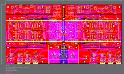
I have just finished half work on the pcb design. Here are Top and Bottom Layers tracks for right channel only. Left will be done later, because I suppose the right tracks need some little changes first. There is not ground plane. I flow the ground plane after any corrections of right channel tracks.
I tried to use symmetrical layout of components and tracks. Nearly all signal and power tracks are placed on bottom layer. Some short signal tracks are on top layer only and servo DC connections are made as top layers tracks.
Have you any comments, please?
Attachments
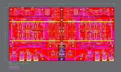
I have just finished the pcb's project: Base Output Audio Board. Maybe some small improvements I will make in next days only. I placed ground plane on top layer only. The ground plane was divided into 6 zones (one channel only):
1. JC-80 amplifier
2. +/-24V Stage PSU and +/-18V Stage PSU
3. DC Servo
4. C6119 decoupling capacitor
5. C6120 decoupling capacitor
6. output audio sockets.
Each zone of ground plane is connected to PSU zone on one end (in one point or common area). I drew it on the ground plane diagram. So each zone of ground plane has empty area (barrier) to other zone. I hope my idea of arrangements of the ground plane is logical and will give some benefits (allow to avoid any troubles with grounding of the amplifier).
On left hand is right channel and on right hand is left channel. Both channels are mirrored to each other. So if you stay before front plate of the amplifier housing you get right sides of channels (right channel on right hand - on right loudspeaker and left accordingly).
On top layer are ground plane, power traces and electronic components only and on bottom layer are signal traces only. Both layers will be gold plated and covered by blue solder masks. Previously I planned to use teflon board instead FR-4 but cost of such big teflon Cu plate is really high.
The pcb is designed exclusively to use: Toshiba transistors 2SK389/2SJ109, Hitachi transistors 2SK214/2SJ77, Caddock resistors TF-020 and MP-820, Vishay resistors TX2352, Vishay trimmers 1280G, Rubycon el-capacitors Black Gate F, MultiCap film capactitors RTX, Icel film capacitors MPW, Vishay-ROE film capacitors MKP1937, Analog Devices op-amps 711/712, Neutrik XLR sockets NC3 series, WBT RCA sockets 805 series and Amphenol BNC sockets B6651 series, Harting connectors DIN41651 and Panasonic relays TQ2. I designed from scratch each footprint for every type of component. Other types of components could be used but they will not fit in holes exactly.
Attachments
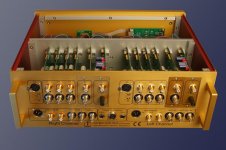
And one detail else: the white two thick lines from left to right edges are Cu bars working as a heat sink for all transistors and TO-220 resistors. And all white rectangular shapes on front of RCA sockets will be cut.
Big holes are for screws to fit PCB in housing, to fit heatsinks and cover of Power Section.
Big holes are for screws to fit PCB in housing, to fit heatsinks and cover of Power Section.
Just finished reading the entire thread. I've been using and been very pleased with the original JC-2 kit from eBay. There is a new "modular" kit available that looks appealing, but this project is intriguing.
Just want to add my support for a possible group buy in the near future. I'm in if/when it happens.
BTW: Spent most of the last two days comparing my JC-2 with a Carver C-1 pushing the BA-3 liquid cooled build. The BA-3 (as configured now) is just short of what I like for "realistic" sound levels - with the speakers I'm using. I don't need a lot of gain, but something based on JC's preamp concepts would be the perfect addition.
Really looking forward to new developments here.")
Just want to add my support for a possible group buy in the near future. I'm in if/when it happens.
BTW: Spent most of the last two days comparing my JC-2 with a Carver C-1 pushing the BA-3 liquid cooled build. The BA-3 (as configured now) is just short of what I like for "realistic" sound levels - with the speakers I'm using. I don't need a lot of gain, but something based on JC's preamp concepts would be the perfect addition.
Really looking forward to new developments here.
- Status
- This old topic is closed. If you want to reopen this topic, contact a moderator using the "Report Post" button.
- Home
- Source & Line
- Analog Line Level
- JC-80 eBay PCBs & Power Train