@keilau
 @gigigirl
Thanks guys for useful information
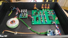
Meanwhile, my package has arrived too and I have tested the board. The board sounds good but as it is almost certain that components are all fake I have initially decided to desolder everything and rebuild it with genuine components.
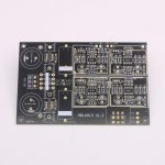
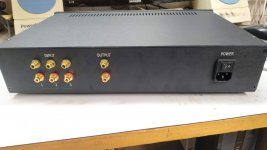
However, I've found a better solution: bare boards of the same 1.2 version (shown on image 1 below) are also available <HERE> and I will build it from the stratch as the board itself seems to be proprtly designed.
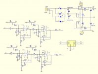
I also have stumbled upon the schematics of the board (shown on image 2). below.
I wish you a pleasant weekend
@gigigirlThanks guys for useful information
Meanwhile, my package has arrived too and I have tested the board. The board sounds good but as it is almost certain that components are all fake I have initially decided to desolder everything and rebuild it with genuine components.
However, I've found a better solution: bare boards of the same 1.2 version (shown on image 1 below) are also available <HERE> and I will build it from the stratch as the board itself seems to be proprtly designed.
I also have stumbled upon the schematics of the board (shown on image 2). below.
I wish you a pleasant weekend
Attachments
Hi gigigirl,
Thanks for the info. I have suspected that there will be some fake parts in the "finisher board" but my original plan was not just to replace the ICs with the original AD979. What I plan to do is to build the preamp from the scratch, with components purchased from Farnell. First I had to wait because AD979 was not on stock.
Now I have purchased two bare boards and everything else will arrive today by UPS from the UK. At least I will know that I have done everything right.
Meanwhile, I have inspected the "completed board" purchased from Aliexpress.
ICs look different just like they have recycled them from used equipment, capacitors have slightly different color from the original Wima, electrolytic capacitors resemble the original, and yet I am suspicious. (Please, read the PS below, regarding these capacitors)
I was astonished to find out that the values of resistors differ from these on the schematics and on the silkscreen: 2K49 instead of 2K2, 12K1 instead of 10K, 205R instead of 220R... It seems like they used resistors with the closest values they could find in the workshop. I simply could not let it be that way.
Now, only components for the preamp cost me about EUR200, without VAT included + costs of the chassis. At least, I know that there will be no junk in my chassis.
Regards
EDIT: Even if you change the thoroidal with the external +/-17 VDC power supply, voltage in the circuits will remain the same: there are two voltage regulators LM317 and LM337 on the board which will keep the same voltage approaching the rest of the circuit. Essentially, you have provided smoother source of power at the input of the existing power supply on the board. This indicates that these "ELNA" capacitors likely are fake.
Last edited:
There is no need to use an external power supply since the existing on-board power supply is adequate, you just have to make proper adjustment. Originally, the board is set to +/- 15.00 VDC. I have adjusted voltage on two 5K potentiometers that are located behind the heat sinks. Now, it measures +/- 17.5VDC. You can measure the positive rail voltage on the IC pin #7. Similarly, the negative rail voltage can be measured in the IC pin #4. Adjust the voltage slowly because response to changes at potentiometers is slow.....So I set the Omishra P/S to +/- 17VDC & ...
Cheers
Furthermore, it is necessary to set voltage drift to zero at all four ICS. As usual, the Chinese instructions are wrong.
Here is how to adjust voltage:
Before you start, observe the board: there are four rectangular areas: the lower two are for the left channel and the upper two rectangles correspond to the right channel.
Also there are two small holes on the PCB between these two 220 uF axial capacitors. You can use them for the ground probe during measurements.
1.
First set the input potentiometer to max volume to have good response to subsequent changes. Otherwise you might see no changes at all if the input potentiometer is set to zero.
2.
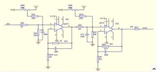
Start with 20K potentiometer LR4 which is located in the lower right rectangular area at the board See the attached schematics. Adjust voltage at IC pin #6 to zero. I have measured that voltage at the left side of 220R resistor located in the lower left rectangle on the board.
3.
Proceed with the 20K potentiometer in the lower left rectangle and measure the voltage at + output of the left channel and G. Now the left channel is adjusted.
4. Repeat the same procedure for the right channel.
Now, the device is ready for use.
I have made some measurements which indicate that the preamp is virtually "a wire with gain" over a very wide range of frequencies. It has entirely flat response between 5Hz and 200KHz.
Cheers
Attachments
Last edited:
There is no need to use an external power supply since the existing on-board power supply is adequate, ...
It is a field where opinions differ
Explain the advantages of an external power supply - YouTube
Many totl preamps have external mains transformers at least
Thanks Ginetto,
Very kind of you. I do appreciate that... but that guy from youtube has another target audience: "audiophiles".
Here, in this particular case, we have at hands more than adequate power supply built into this preamp. Furthermore, this power supply is linear, regulated, and adjusted to +/- 15.00 VDC by default, but fortunately, still adjustable. If we connect it in series with another power supply with higher voltage, we will end up again with 15 VDC because that 220R along with the 5K pot define the output from LM317 / LM337 pair to +/- 15.00 VDC. The only "benefit" from this is dissipation of heat needed to drop the extra voltage through the heat sink. Nothing else. If one can hear any difference it is, unfortunately, audiophile placebo effect.
Hence the only way to change the voltage at the IC in this circuit is to select another value at the potentiometer. May I suggest you to read reliable technical document linked below at TI, not youtube Fake News.
No offense meant, this is strictly technical matter.
https://www.ti.com/lit/ds/symlink/lm317.pdf
Last edited:
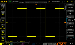
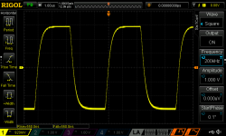
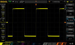
Now, let me present a couple of measurements at the extremes: 5Hz, and 200KHz along with the response to 10 KHz wave.
In all three cases we have 1V square wave at the input.
In all three cases we have 1V square wave at the input.
Attachments
Last edited:
Thanks Ginetto,
Very kind of you. I do appreciate that... but that guy from youtube has another target audience: "audiophiles".
https://www.ti.com/lit/ds/symlink/lm317.pdf
Hi no offense taken ... no problem. I just like the man and i think he is honest in his story. Personally even if measurements do not tell of any issues to have the mains transformer inside the same case of the circuits board ... i do not like it. I much prefer to place the transformer outside and maybe put a lot of capacitance very close to the board circuit (energy storage). Actually is what i am thinking to do with one preamp i have at hand which has the mains transformer even soldered on the same board of the circuit ... i am even thinking to cut the board in two parts ... one the circuit ... the other the transformer on small rubber feet and shielded with copper.
Dear Ginetto,
Lo so che lei è una persona gentile, e lo apprezzo molto.
Sometimes I have impression that sales departments want to ensure us that measurements mean nothing and then tell convincingly that customers gut feeling is the best basis for judgement. Then they have us in their pockets or should I say they have their hands in our pockets. For good music, girls, vine or meals that's the right reasoning but with technical stuff it is quite different thing. For example, i prefer classical music and the right choice is to select neutral audio equipment, which doesn't change the recording. From preamplifier I expect just verbatim gained copy of the input signal.
This preamplifier does exactly that: it doesn't sound at all it is dead silent and has an adequate response to the input signal.
I have two units and will build the third from verified components. Interestingly, Chinese "complete board" is rather fine, almost exactly the same I have built from the scratch. Except mine has better response to square waves: it consistently responds faster to square signal over the entire measuring range.
This is very good product.
Saluti!
Last edited:
Thanks Ginetto,
Very kind of you. I do appreciate that... but that guy from youtube has another target audience: "audiophiles".
Hi ! i see your point and my brain of course tells me that you are very right.
But i am always torn between reason and feeling
For instance tube preamps/amps are clearly electrically inferior to solid state ones (i.e. higher noise and distortion)
Nevertheless someone love their sound so much more than solid state sound
Hi, Well as far as I know from their blurb the 1st pair of op-amps are an input buffer!! Whatever that means.
Anyway I received my Chinese AD797 op-amps today. Yes I know they are fake, but have used them before for testing my phono amp, then I replaced them with genuine one. The genuine ones definitely sounded better, but it was not night & day, they were very close.
So how did they sound, well initially very good, better that the 55 series, definitely brighter. I have left the playing on repeat in my 2nd system. I will do a more serious listen in a couple more days.
Also it occurred to me that the from pair of dual op-amps could be replaced with one of the many available, any suggestions.
Cheers
I picked up a few chinese 'muses' few wks ago and based on the prices, they gotta be fakes.
But they actually sound good, esp the muses01, without being over-analytical, that kinda in-your-face clarity.
No experience with tl082. The one I took out was lm4562
Hi i was referring to a viable opamp for a fake muses01. And 1USD part can be sold for 10 times its price
Thanks for the info.
I haven't made partial replacements. I have changed everything, altogether: with components purchased from Farnell (reputable UK supplier from Leeds). Just the bare board was from China (Aliexpress).
Meanwhile, I have returned to the original +/-15.00 VDC because there were no benefits from the increase of the rail voltages to +/-17.5VDC. Also, the data sheet indicates that the maximum value is 18.00VDC.
But...
I am confused with your information that your board does not have regulated power supply. Are we talking about the same board?
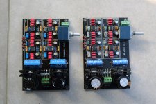
Below, I have attached a photo of Chinese board (right), and the board I have assembled (left). Note the different parts.
Regards.
I haven't made partial replacements. I have changed everything, altogether: with components purchased from Farnell (reputable UK supplier from Leeds). Just the bare board was from China (Aliexpress).
Meanwhile, I have returned to the original +/-15.00 VDC because there were no benefits from the increase of the rail voltages to +/-17.5VDC. Also, the data sheet indicates that the maximum value is 18.00VDC.
But...
I am confused with your information that your board does not have regulated power supply. Are we talking about the same board?
Below, I have attached a photo of Chinese board (right), and the board I have assembled (left). Note the different parts.
Regards.
Attachments
Last edited:
Ah, I see now, we have different boards: this is yours:Hi, One of the problems we have with this thread is that we are often taling about different board.
I upgraded my P/S because I was getting a little hum, now it is dead quite, however my Pre Amp board did not use 317/337 voltage regulators & had no voltage adjustment on the power supply of the board.
I have now replaced the cheap & cheerful V/C with a Tocos unit, which has opened things up a bit more & noticeably improved the top end.
Cheers
HIFI MBL6010D Preamplifier Preamp Board Tone adjust Fit For NE5532 NE5534 OPA 228243292918 | eBay
The 5534 nulls to V+ on pins 1 and 8. The 797 to V- on pins 1 and 5. There will be equal resistors if measured at the pins (make sure the voltage burden of your meter is <.5V or you might see an ESD diode). Jan, the fakers can't do anything about the pin out.
Thank you for quick tip. I just measured SOIC AD797BRZ's that I bought from Aliexpress couple years back then.
The nulling pins, Pin1 and Pin5 measure exactly 1000 Ohms each to the V- pin as you described. I don't know the original value of the resistance.
They were arrived in sealed reel sheet. But pressed numbers at bottom varies like 48D04, 48C50, 48C62 which looks fishy. Probably numbers must be same if they were really on same reel. I never used them to judge their performances btw.
- Home
- Source & Line
- Analog Line Level
- AD797 Preamp based on stolen trademark