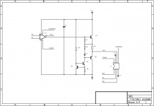
This is an announcement of the LF01 discrete/hybrid module that uses a monolithic SOIC-8 single opamp, some BJTs and passives and plugs into a DIP-8 single-opamp socket. The intent is to bias the output stage of the opamp into Class-A, the discrete output stage into Class-A/AB and bypass the current limit of the monolithic opamp (more details will follow later).
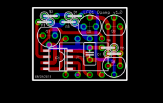
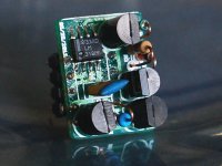
Schematic, Layout and picture of a prototype with an LM318 installed - this is intended for the MyRef Rev C:
Schematic, Layout and picture of a prototype with an LM318 installed - this is intended for the MyRef Rev C:
Attachments
Preliminary BoM for the LF01/LM318M prototype (for use in the MyRef RevC):
R1: 1k/0.125w/5% CFR
R2: 10r/0.125w/5% MFR
R3: 4.7r/0.25w/5% CFR
R4: 33k/0.25w/1% MFR
R5: 150r/0.125w/5% CFR
C1: 10nF X7R or C0G ceramic plate-type
D1: 1n4148
Q1, Q3: 2sc1815Y
Q2: 2sa1015Y
Q4: 2sc1845
IC1: NatSemi LM318M
R1: 1k/0.125w/5% CFR
R2: 10r/0.125w/5% MFR
R3: 4.7r/0.25w/5% CFR
R4: 33k/0.25w/1% MFR
R5: 150r/0.125w/5% CFR
C1: 10nF X7R or C0G ceramic plate-type
D1: 1n4148
Q1, Q3: 2sc1815Y
Q2: 2sa1015Y
Q4: 2sc1845
IC1: NatSemi LM318M
Are any other mods to the amp required? Must your Ref C boards be used? Will this be stable with the standard PS regulation of the current Ref C?
Boards available when?
Thanks - the first tests were actually done with a V1.2 board. There may be mechanical interference with R3 and C6. A Futaba MPC74 at R3 and low-profile electrolytics (say Black Gate PK) at C6/C11 solves the clearance issue on V1.2 Twisted Pear boards.
It should also fit and work fine with my V1.3/1.4 boards, but I haven't yet tried it out. It appears to be stable and sounds fine with the components listed, but some further tweaking of resistor values may be necessary for optimizing the sonics.
The bare boards are available now; kits and assembled boards may have to await some tweaking of the passives - say 2-4 weeks.
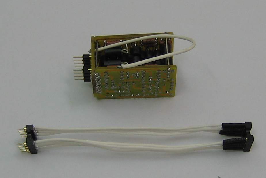
so it doesn't fit in 1.2 board if say silmics are installed at c6/11? how about running it through a wire off board like this?
p.s. sign me up for one regardless :thumbsup:
An externally hosted image should be here but it was not working when we last tested it.
p.s. sign me up for one regardless :thumbsup:
the opamp was chosen by the designer to complement the unusual topology of the MyRefC.
My RefC was then compensated with the chosen opamp in place.
Swapping opamps is discouraged because that will almost certainly require the compensation of MyRefC to be altered.
It appears Linux is using the characteristics of the same opamp and it's own compensation to avoid changing the compensation of the MyRefC.
Admirable criteria.
so what are the sonic benefits of this module? i bet everything's better but specifically, does it cure that last bit of hardness which they say is due to the op-amp?
I'm actually not sure if the slight residual edginess is due to the opamp, the chipamp, the topology, the quality of the passives or any/all of the above. I'm hoping that the LF01 reduces the contribution from the opamp output stage, with some tweaking on the LF01 alone if necessary.
The first impressions are that the imaging is tighter and the soundstage is wider, but I'll defer on this claim until some other experienced listeners have auditioned it on a wider range of tracks.
It appears Linux is using the characteristics of the same opamp and it's own compensation to avoid changing the compensation of the MyRefC.
Yup, exactly. It may still require a few components to be changed on some boards, but that will be due to clearance/physical size issues.
why not omit the opamp all together?
The discrete output stage of the LF01 is only a unity-gain buffer/voltage follower - you'll still need an input stage and a VAS. This could be made fully-discrete, but the module will be larger and may have no advantage over many high-performance opamps (LT1028, OPA627, OPA1611, etc.).
I sought to combine the advantages of high-performance monolithic opamps (low noise, high PSRR, high CMRR, low distortion, small physical footprint, relatively low quiescent current, etc.) with the advantages of a discrete output stage (Class-A operation, no current limit). The main intent was to drive low-impedance loads, including headphones, without clipping. It turns out that it also works pretty well for most opamp applications (except micro-power, precision offset, and low-voltage/rail-to-rail applications).
so it doesn't fit in 1.2 board if say silmics are installed at c6/11? how about running it through a wire off board like this?
Yup, if you have tall caps flush-mounted at C6/C11, the LF01 may not fit in the socket. If C6 has sufficient lead length to bend it aside, it might still fit.
If you use a socket-extender cable, you'll have to worry about lead-inductance and cross-talk, especially on the comp and comp/bal pins. The LM318 is extremely fast, despite its age. With much slower opamps (eg. LM741 or TLV2341), an extender cable may work just fine, but you probably don't want to use such opamps in high-end audio.
Preliminary BoM for the LF01/LM318M prototype (for use in the MyRef RevC):
R1: 1k/0.125w/5% CFR
R2: 10r/0.125w/5% MFR
R3: 4.7r/0.25w/5% CFR
R4: 33k/0.25w/1% MFR
R5: 150r/0.125w/5% CFR
C1: 10nF X7R or C0G ceramic plate-type
D1: 1n4148
Q1, Q3: 2sc1815Y
Q2: 2sa1015Y
Q4: 2sc1845
IC1: NatSemi LM318M
Changed R1 to: 470R/0.125W/1% MFR (probably makes no difference if it is 5% CFR). This biases the LM318 deeper into Class-A with ~1.5 mA quiescent current, and the audible sonics seem to be smoother, more airy, and less fatiguing. This is in a stock MyRef RevC in a Twisted Pear V1.2 board.
Related query: Are there stacked film/foil polypropylenes available in 2.5mm lead pitch, e.g. Wima FKP02, and what's the highest capacitance value available?
Hi Siva,
Received the board in a fine condition today, and what a fine board it is! I couldn't believe how tiny the pcb was, and still can't believe how I managed to fit FKP02 100nf in there.")
Sonic impressions will be done later today.
Thank you for this wonderful offering.
Received the board in a fine condition today, and what a fine board it is! I couldn't believe how tiny the pcb was, and still can't believe how I managed to fit FKP02 100nf in there.
Sonic impressions will be done later today.
Thank you for this wonderful offering.
Received the board in a fine condition today, and what a fine board it is! I couldn't believe how tiny the pcb was, and still can't believe how I managed to fit FKP02 100nf in there.
Thanks - please take your time and assemble it carefully and check for bridges, shorts, etc.
You may need to piggyback it on one or more DIP sockets to be able to clear some components on a V1.2 board - YMMV.
I'm a bit envious that you were able to get a Wima FKP02 - the best I can manage here are MKS02 in 1nF and 3.3nF, which are pretty good actually. I'll try to upgrade to FKS02/FKP02 if I can get hold of them. AVX or Kemet Aximax C0G in 10 nF are also pretty good for C1.
wow, yes siva! the sound is definitely smoother and richer in harmonics->warmer.
This is indeed a step toward the right direction for myrefc.
I had to move the c5 cap underboard to make room for the module, but the tiny holes in the pcb soaked up the flux easily, despite my worries.
All in all, a hassle free operation and another testament to the wonderful quality of your boards.
Oh, and FKP2 is just a beginning. I plan on replacing it with a 'proper' tubelar mkp cap connected via lead wiring much like how I retrofitted mundorf supreme caps underboard for c4,7 on my myref. they certainly sound miles better than any through hole caps I've tried.
I used a similar approach, but for much higher output currents here:-
http://hifisonix.com/wordpress/wp-c...niversal-Small-Signal-Class-A-Buffer-V1.0.pdf
This does not use the same op-amp, but uses a similar biasing trick to force the output stage into class A.
Good luck with your project - looks quite neat I have to say!
http://hifisonix.com/wordpress/wp-c...niversal-Small-Signal-Class-A-Buffer-V1.0.pdf
This does not use the same op-amp, but uses a similar biasing trick to force the output stage into class A.
Good luck with your project - looks quite neat I have to say!
wow, yes siva! the sound is definitely smoother and richer in harmonics->warmer.
...
Oh, and FKP2 is just a beginning.
Thanks Eric, my observations are similar - the sonics seem smoother and airier, with typical Class-A warmth.
I'd recommend staying with the FKP02, but maybe with a smaller value - say 10 nF. The alternative is a polystyrene, but it will be difficult to find a 10 nF that fits in the 2.5mm pitch provided.
BTW, how do you manage to rework the PCB to change parts? It's very difficult to get to the pins of C1 after the module pin headers (4 + 4 pins) are in place.
I used a similar approach, but for much higher output currents here:-
http://hifisonix.com/wordpress/wp-c...niversal-Small-Signal-Class-A-Buffer-V1.0.pdf
This does not use the same op-amp, but uses a similar biasing trick to force the output stage into class A.
Bonsai - thanks for the link. You have much higher output stage bias currents, which I've reduced a great deal by using Class-A Push-Pull with a PNP in the output stage. I also use smaller bias current (~1..1.5 mA) for the opamp output stage bias.
There's also an unusual biasing trick in my circuit that allows reverse current flow in the emitter degeneration resistor of the NPN in the output stage, thus keeping the upper half from cutting off hard, even at large swings - check it out in LTSpice to get the full picture.
well I'm a bit of a barbarian when it comes to soldering. I'd use a dulled out tip that has enough contact area to heat both pins at once and pull the cap out as the solder melts.
Of course there's the risk of melting the plastic of the surrounding pin headers but I wouldn't call myself a barbarian if I was afraid of that.
Of course there's the risk of melting the plastic of the surrounding pin headers but I wouldn't call myself a barbarian if I was afraid of that.
- Status
- This old topic is closed. If you want to reopen this topic, contact a moderator using the "Report Post" button.
- Home
- Source & Line
- Analog Line Level
- ANN: LF01 Discrete/Hybrid Opamp Module