Lineup and me we have designed a line level preamplifier, just for fun  . It is based on our discrete module (upgrade of D. Jensen 918) that is also used in our phono preamplifier. There is a module called "JISBOS" and because we use exclusively BJTs from input to output we gave the name "BISBOS" to our discrete OpA. Benefits of BISBOS: 1) No expensive and hard to find jfets for input stage, just ordinary BC550C-560C 2) No need for excess class A idle current 3) No need for matching input transistors, output DC offset can be precisely adjusted from the trim-pot of LTP. 4) Same performance with JISBOS in unity gain (voltage follower) connection. 5) No need for complex power supply / stabilizer circuit, ordinary LM317-337 can do the work, just fine.
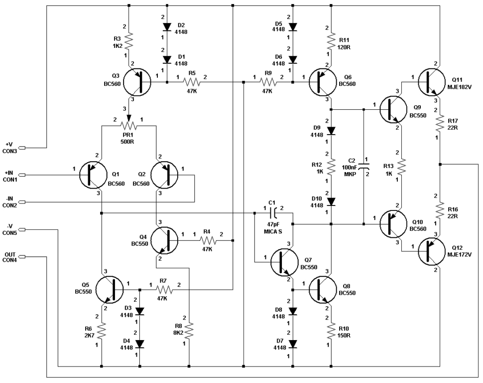
Here the schematic of... BISBOS:
. It is based on our discrete module (upgrade of D. Jensen 918) that is also used in our phono preamplifier. There is a module called "JISBOS" and because we use exclusively BJTs from input to output we gave the name "BISBOS" to our discrete OpA. Benefits of BISBOS: 1) No expensive and hard to find jfets for input stage, just ordinary BC550C-560C 2) No need for excess class A idle current 3) No need for matching input transistors, output DC offset can be precisely adjusted from the trim-pot of LTP. 4) Same performance with JISBOS in unity gain (voltage follower) connection. 5) No need for complex power supply / stabilizer circuit, ordinary LM317-337 can do the work, just fine.Here the schematic of... BISBOS:
Attachments

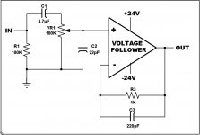
Block diagram of preamplifier
Here is the block diagram indicating the external parts connected around the discrete OpA. Cap C2=22pF is used to compensate the input impedance affected from the 100K log volume potentiometer. Sorry guys, i have in my stock only two such pots and no money to buy a 10K.
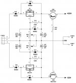
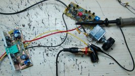
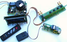
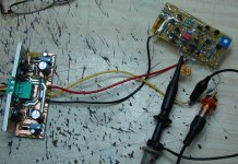
Besides, is the schematic of voltage stabilizer unit, which is calibrated in +/-24V instead the +/-22V indicated. You can also see a photo of the trial unit on the workbench:
Here is the block diagram indicating the external parts connected around the discrete OpA. Cap C2=22pF is used to compensate the input impedance affected from the 100K log volume potentiometer. Sorry guys, i have in my stock only two such pots and no money to buy a 10K
.Besides, is the schematic of voltage stabilizer unit, which is calibrated in +/-24V instead the +/-22V indicated. You can also see a photo of the trial unit on the workbench:
Attachments
Performance
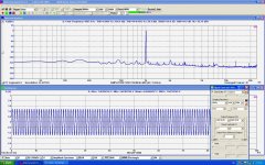
Here the most interesting part: The performance of the whole circuit captured from the Virtins MI analyzer. To be sincere, when i saw for first time the results i could not believe in my eyes! For this reason i did again and again (at least 10 times) the FFT analysis to be sure. The result was the same. The numbers are too close to those of the Asus Xonar Essence STX that i use as interface! I haven't did yet an audition test. The numbers indicate an almost transparent circuit, with the volume pot at 100% and an input signal of 1.41Vrms (0dBV). In the first picture is shown the performance in Un-weighted mode, and in the second in A-weighted.
Here the most interesting part: The performance of the whole circuit captured from the Virtins MI analyzer. To be sincere, when i saw for first time the results i could not believe in my eyes! For this reason i did again and again (at least 10 times) the FFT analysis to be sure. The result was the same. The numbers are too close to those of the Asus Xonar Essence STX that i use as interface! I haven't did yet an audition test. The numbers indicate an almost transparent circuit, with the volume pot at 100% and an input signal of 1.41Vrms (0dBV). In the first picture is shown the performance in Un-weighted mode, and in the second in A-weighted.
Attachments

Bandwidth
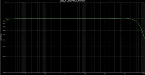
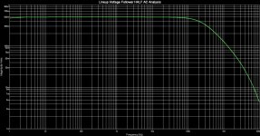
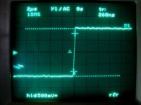
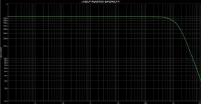
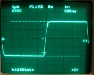
Here is the bandwidth captured from simulator. Unfortunately, sound cards have a max bandwidth of 192Ks/sec : 2 = 96KHz. So, they are unsuitable for bandwidth measurement. In the 1st picture is shown the bandwidth with the vol pot at 100% (no attenuation) and is amazing good, very close to JISBOS (this proves that the bandwidth is an issue of topology and not of the type of semiconductors used). In the second picture is shown the bandwidth with the vol pot at 50% (50% attenuation of input signal) For the suspicious (i am one of them ) in the 3rd picture i attach a capture from my DSO , where the rise time is just 260nsec for a square of 10KHz. A square of 100KHz gives a rise time of 300nsec.
Here is the bandwidth captured from simulator
. Unfortunately, sound cards have a max bandwidth of 192Ks/sec : 2 = 96KHz. So, they are unsuitable for bandwidth measurement. In the 1st picture is shown the bandwidth with the vol pot at 100% (no attenuation) and is amazing good, very close to JISBOS (this proves that the bandwidth is an issue of topology and not of the type of semiconductors used). In the second picture is shown the bandwidth with the vol pot at 50% (50% attenuation of input signal) For the suspicious (i am one of them ) in the 3rd picture i attach a capture from my DSO , where the rise time is just 260nsec for a square of 10KHz. A square of 100KHz gives a rise time of 300nsec.Attachments
Output noise & DC offset
I ask your forgiveness for my spelling errors. I am self-taught in English. In high school (1970 - 1976) we were taught French. Now, i have forgot French and i haven't any one to talk English. Big problem.
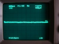
Here is a DSO capture indicating the output noise. It is so small, that the DSO can't compute in RMS so easy; in AVG mode it shows values between 125μV to 250μV. The output DC offset is a "clear zero".
I ask your forgiveness for my spelling errors. I am self-taught in English. In high school (1970 - 1976) we were taught French. Now, i have forgot French and i haven't any one to talk English. Big problem.
Here is a DSO capture indicating the output noise. It is so small, that the DSO can't compute in RMS so easy; in AVG mode it shows values between 125μV to 250μV. The output DC offset is a "clear zero".
Attachments
Remote control
I have ready - 5 months ago - a manually / remotely control unit based on a PIC16F887 micro. I developed the mcu code using the nice programming software Flowcode v4 of Matrix Multimedia. The program is written in such way, so as the PIC16F887 can manage Latching type relays. A complete description of this unit here: http://www.eal.gr/MICROS.htm
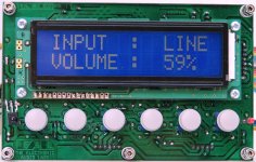
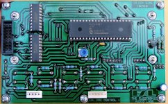
Here some pictures of control unit.
I have ready - 5 months ago - a manually / remotely control unit based on a PIC16F887 micro. I developed the mcu code using the nice programming software Flowcode v4 of Matrix Multimedia. The program is written in such way, so as the PIC16F887 can manage Latching type relays. A complete description of this unit here: http://www.eal.gr/MICROS.htm
Here some pictures of control unit.
Attachments
Last edited:
Inverter
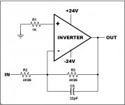
We have the idea to include and a balanced output in our preamplifier. To this, i checked the... BISBOS in inverting mode with Av = 1. The results of test are very good.
Here is the schematic and a picture of module on workbench:
We have the idea to include and a balanced output in our preamplifier. To this, i checked the... BISBOS
in inverting mode with Av = 1. The results of test are very good.Here is the schematic and a picture of module on workbench:
Attachments
Inverter performance
Here are the results of FFT analysis captured from Virtins MI FFT software. In the first picture is the performance in Unweighted mode. In the second is in A-Weighting mode. Again an almost transparent circuit.
Here are the results of FFT analysis captured from Virtins MI FFT software. In the first picture is the performance in Unweighted mode. In the second is in A-Weighting mode. Again an almost transparent circuit.
Attachments


Last edited:
Inverter Bandwidth
Here is the bandwidth of Inverter captured from... simulator. For verification, i attach a second picture that shows the rise time of a 100KHz square wave, captured from DSO.
Here is the bandwidth of Inverter captured from... simulator
. For verification, i attach a second picture that shows the rise time of a 100KHz square wave, captured from DSO.Attachments
Keep up the good work, guys!
Fotios, if you want a new challenge, check this one out: Weiss Engineering OP1-BP discrete opamp
[Not responsible for any sleepless night that may result from reading the above datasheet]
Fotios, if you want a new challenge, check this one out: Weiss Engineering OP1-BP discrete opamp
[Not responsible for any sleepless night that may result from reading the above datasheet
]
Last edited:
Keep up the good work, guys!
Fotios, if you want a new challenge, check this one out: Weiss Engineering OP1-BP discrete opamp
[Not responsible for any sleepless night that may result from reading the above datasheet
Thanks Shaman for supporting us.
As for Weiss Engineering, this guy has been escaped completely!
And you bre Kostas, you always find such types! Aman!
I live in Greece, a country with poor means for experimenting and investigation, especially for us "τους παροικουντες την Ιερουσαλημ" in north Greece. I have just a sound card and a cheap FFT software for making tests. If i had the same instruments like Weiss...
OTOH our discrete, it is a good device. We (Lineup and i) never claimed that is the super-duper OPA. It is just a fair circuit - based on other circuit and improved thru simulation - and nothing else.
..... breathless fotios ... well done ...
Ah bre Sakis... all of us the self-employed in Greece we are in the mouth of IMF.
Thanks friend.
Fotis
hi,
pardon my ignorance but can you enlighten me about Q9 and Q10, this is the first time ive' seen such arrangement....
Tony, this arrangement is an invention of Lineup. In practice, is a thermal compensation of output transistors providing lower 2nd and 3rd harmonic compared to the 2 diodes usually used in this place. Since is first presented, rightfully takes the name LINEUP THERMAL COMPENSATION. I wish you Lineup, a place in the stars of galaxy where they live the wise men of our world (and not a place in Guinness world record book).
Your devoted friend Lineup
Fotis
thanks fotios.....i see there are 2 other diodes and i thought these trannies were redundant...
thanks fotios.....i see there are 2 other diodes and i thought these trannies were redundant...
Thanks and in you Tony. In reality, the 2nd and 3rd harmonics are reduced by 1 to 3 dB. Nothing extreme
(sorry Lineup). OTOH, you know that transistors have the Beta (hfe) factor, instead diodes. So, more accurate behavior in frequency variations. You know that, for the same reason in current mirrors is used a transistor connected as diode instead a simple diode.Have a nice day (or night in Philippines)
Fotios
- Home
- Source & Line
- Analog Line Level
- Preamplifier from Lineup & Fotios for fun