I don't think I ever complete an Arduino PGA2310 project.
I made another preamp, details are here:
http://www.diyaudio.com/forums/anal...eamp-arduino-remote-volume-input-control.html
And you can find the code here:
https://github.com/FutureSharks/preamp-v1
Or a passive one here:
http://www.diyaudio.com/forums/anal...remote-control-relay-r2r-input-selection.html
And you can find the code here:
https://github.com/FutureSharks/preamp-passive
Maybe you can find some useful code in there")
Hey Max, that looks really nice (your previous preamp too btw
 ). What's the Johnson noise like though with that many large resistors (in the passive preamp)?
Would you choose the DAC8812 again today or do you feel there are better alternatives available?
I don't think I ever complete an Arduino PGA2310 project.
I made another preamp, details are here:
http://www.diyaudio.com/forums/anal...eamp-arduino-remote-volume-input-control.html
And you can find the code here:
https://github.com/FutureSharks/preamp-v1
Or a passive one here:
http://www.diyaudio.com/forums/anal...remote-control-relay-r2r-input-selection.html
And you can find the code here:
https://github.com/FutureSharks/preamp-passive
Maybe you can find some useful code in there
Hi max
Thank you very much!
I actully mange to work with arduino and the pga3210 flawlessly!
No noise, no jams, no nothing, just perfect!
I used the recommended schemetics in the datasheet, no more no less.
I'm not sure. Can you hear "Johnson noise"? Or do you measure it?Hey Max, that looks really nice (your previous preamp too btw
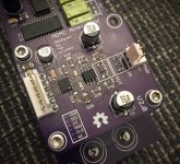
I think it's still the best. Unless you can find another 16bit R2R that is SPI controlled. I actually just made a new design using this IC but it's really just a slightly different layout and without the isolation IC (photo attached).Would you choose the DAC8812 again today or do you feel there are better alternatives available?
Excellent. I always had some background noise with my PGA2310s.Hi max
Thank you very much!
I actully mange to work with arduino and the pga3210 flawlessly!
No noise, no jams, no nothing, just perfect!
I used the recommended schemetics in the datasheet, no more no less.
Attachments
AFAIK it'd be white noise if you'd hear it. If not, well, then it's not too large.I'm not sure. Can you hear "Johnson noise"? Or do you measure it?
Why change a winning formula, eh?I think it's still the best. Unless you can find another 16bit R2R that is SPI controlled. I actually just made a new design using this IC but it's really just a slightly different layout and without the isolation IC (photo attached).
Really dig the original approach you took with this design, using the signal as the reference voltage for the DAC.AFAIK it'd be white noise if you'd hear it. If not, well, then it's not too large.
I think there is always some noise when using a passive attenuator, including a pot.
Thanks but I just copied some other implementations, chose some parts and designed some PCBs. My actual electrical engineering knowledge is very limitedWhy change a winning formula, eh?
Hi max.
Ok, now i can a small problem, its not so noticeable, only when standing really close to the monitor i can hear the steps going up and down.
Im using a regular pot.
Do you by any chance have a solution for that?
I don't understand. Are you using a pot? Or PGA2310?
Have you got zero crossing enabled, i.e., pulled ZCEN (pin 1) high?Im using a pot to control 8 X PGA2310 via arduino. Now only one is conected for testing
Have you got zero crossing enabled, i.e., pulled ZCEN (pin 1) high?
Yes i am.
Do you think i should connect it via 10k resistor to 5V or connect it direct is ok?
I must remind you im using regular 100k anlog pot, so when i turn it all the way its going up very fast unlike the encoder that i need to turn for ever to have max Volume.
Yes i am.
Do you think i should connect it via 10k resistor to 5V or connect it direct is ok?
For the very similar PGA2320 I connected it through a 10K resistor. It works fine, but I don't recall reading about it in the datasheet. I've seen a few other designs that also used a resistor to connect ZCEN to the 5V rail.
I must remind you im using regular 100k anlog pot, so when i turn it all the way its going up very fast unlike the encoder that i need to turn for ever to have max Volume.
Hmm, I'm controlling the IC using an Arduino that reads an encoder. How exactly would you use an analog pot here? Do you have it wired to an analog input on your microcontroller or something like that? And, if that's what you're doing, whether it goes fast or slow simply depends on how you map your input to whatever volume you send to the PGA IC, doesn't it?
Last edited:
For the very similar PGA2320 I connected it through a 10K resistor. It works fine, but I don't recall reading about it in the datasheet. I've seen a few other designs that also used a resistor to connect ZCEN to the 5V rail.
Hmm, I'm controlling the IC using an Arduino that reads an encoder. How exactly would you use an analog pot here? Do you have it wired to an analog input on your microcontroller or something like that? And, if that's what you're doing, whether it goes fast or slow simply depends on how you map your input to whatever volume you send to the PGA IC, doesn't it?
the 10k dose not appear in the datasheet.
ill do that, thank you.
i use arduino as well and yes, it goes to A0 input.
i dont really know how to write a code, i have friend that helps me out.
the reason i'm not using an encoder is that i didnt mange to work it out with encoder.
could you help me out with code and scheme for the encoder please?
what kind/type of encoder you used, any link?
i thank you in advanced.
have a great day
Sure, if you're using an Arduino Uno / Genuino Uno, this would probably be the best way:
- Install the library from https://www.pjrc.com/teensy/td_libs_Encoder.html (see: Installing Additional Arduino Libraries);
- Wire the rotary encoder channels to digital pin 2 and pin 3 on the Arduino (those support hardware interrupts) and be sure to provide the encoder with 5V;
- Include the library in your program and use the example code from the link above to read from the encoder.
As for the encoder itself, I'm using a Bourns EM14 optical encoder as my setup requires an encoder with a momentary switch. If you don't need such functionality you can also get encoders with higher resolutions, for example, that support 64 changes per revolution.
This page on the Arduino website also has a lot of good information on using rotary encoders: Reading Rotary Encoders Contents
Thank you very much
I decided to stay with analog pot cause of the feel of the touch
I really need to solve the clicking ticking noise problem.
When googling obout this issue it turns out to be a DC offset.
Having a look at the datasheet of the PGA2310, TI says its should be 3mV DC offset, when the PGA2311 is only 0.5mV DC offset but the PGA2311 should work only with 5(+)(-)V.
I really think that the PGA2311 will have better results then the PGA2310.
i will have to order one to confirm this.
Last edited:
fwiw, I also have a pga project going on right now. link to the forum where a lot of discussion is happening:
AMB Laboratories DIY Audio • View topic - TI PGA23xx solid state volume control chip support
will be entering public beta test soon and boards are working nicely so far. software still under devel with some new interesting features being added.
AMB Laboratories DIY Audio • View topic - TI PGA23xx solid state volume control chip support
will be entering public beta test soon and boards are working nicely so far. software still under devel with some new interesting features being added.
- Status
- This old topic is closed. If you want to reopen this topic, contact a moderator using the "Report Post" button.
- Home
- Source & Line
- Analog Line Level
- Arduino controled PGA2310 Preamp