When you fit a new reg, don't overtighten and make sure that the metal back of the reg DOES NOT read short or "zero" ohms to the metal work of the heatsink and chassis. That just makes sure the insulating washer and bush is OK. You will get a reading of some kind with it in circuit but NOT short ")
Fixed by tea time... yes, yes
gota go
Fixed by tea time... yes, yes
gota go
Same
Mooly,
Replaced the reg. Removed the fuse, installed a paralleled pair of 1 watt, 2 ohm resistors - still no tuner.
VOLTAGE AT REG: 0.17 volts
VOLTAGE ACROSS "FUSE": 28.4 volts
VOLTAGE AT PIN 11: 0.17 volts
Too bad - I was hoping for a little celebration.
What to do next?
Thanks!
Mooly,
Replaced the reg. Removed the fuse, installed a paralleled pair of 1 watt, 2 ohm resistors - still no tuner.
VOLTAGE AT REG: 0.17 volts
VOLTAGE ACROSS "FUSE": 28.4 volts
VOLTAGE AT PIN 11: 0.17 volts
Too bad - I was hoping for a little celebration.
What to do next?
Thanks!
Attachments
Last edited:
That's a pity, it appears in this case there is something drawing excessive current.
Ideally a separate current limited lab power supply could be used to power the 12 volt rail and allow you to work on it.
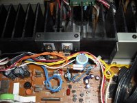
Faultfinding now consists of isolating items on that rail, initailly by disconnecting pin 4 of CN31 and confirming the regulator output is OK with no load. The fault could now be any component that has the ability to present a low impedance across the supply. So that could be any decoupling cap of any type across the rail or any IC fed of that rail directly. It's common practice practice with anything like this to try and split the circuit in halves to try and locate the problem, perhaps disconnect the tuner pcb.
The other real issue is keep blowing fuses. It moght be worth trying the "light bulb" tester in the mains lead to limit current. Make sure the unit powers up OK with say a 100 watt bulb, and then start again. A shor on that rail should cause the bulb to light brightly, it may even allow sufficient current to flow such that the problem becomes apparent such as a cap getting hot or an IC burning etc. Sounds drastic but without a full range of test gear your options are limited.
If the bulb lights brightly indicating large current flow another good way is to measure the volt drop across PCB tracks. Although the voltage will be in the milivolt range it will show up a piece of print carring excess current.
Ideally a separate current limited lab power supply could be used to power the 12 volt rail and allow you to work on it.
Faultfinding now consists of isolating items on that rail, initailly by disconnecting pin 4 of CN31 and confirming the regulator output is OK with no load. The fault could now be any component that has the ability to present a low impedance across the supply. So that could be any decoupling cap of any type across the rail or any IC fed of that rail directly. It's common practice practice with anything like this to try and split the circuit in halves to try and locate the problem, perhaps disconnect the tuner pcb.
The other real issue is keep blowing fuses. It moght be worth trying the "light bulb" tester in the mains lead to limit current. Make sure the unit powers up OK with say a 100 watt bulb, and then start again. A shor on that rail should cause the bulb to light brightly, it may even allow sufficient current to flow such that the problem becomes apparent such as a cap getting hot or an IC burning etc. Sounds drastic but without a full range of test gear your options are limited.
If the bulb lights brightly indicating large current flow another good way is to measure the volt drop across PCB tracks. Although the voltage will be in the milivolt range it will show up a piece of print carring excess current.
That's a pity, it appears in this case there is something drawing excessive current.
Ideally a separate current limited lab power supply could be used to power the 12 volt rail and allow you to work on it.
Faultfinding now consists of isolating items on that rail, initailly by disconnecting pin 4 of CN31 and confirming the regulator output is OK with no load. The fault could now be any component that has the ability to present a low impedance across the supply. So that could be any decoupling cap of any type across the rail or any IC fed of that rail directly. It's common practice practice with anything like this to try and split the circuit in halves to try and locate the problem, perhaps disconnect the tuner pcb.
The other real issue is keep blowing fuses. It moght be worth trying the "light bulb" tester in the mains lead to limit current. Make sure the unit powers up OK with say a 100 watt bulb, and then start again. A shor on that rail should cause the bulb to light brightly, it may even allow sufficient current to flow such that the problem becomes apparent such as a cap getting hot or an IC burning etc. Sounds drastic but without a full range of test gear your options are limited.
If the bulb lights brightly indicating large current flow another good way is to measure the volt drop across PCB tracks. Although the voltage will be in the milivolt range it will show up a piece of print carring excess current.
1. Is it OK to continue using the resistor instead of the fuse?
2. I recapped the entire controller board, and about half the main pcb. While this is the "shotgun" approach, would you recommend finishing recapping the main board?
3.RE: Disconnecting pin 4 of CN31 - how does one confirm the regulator output is OK with no load (what you're saying is that the new reg might be bad?)
Thanks again for your help and have a Happy Christmas!
1. If the resistor has 28 volts across it (that is 28 on one end and zero on the other) then it is open circuit. Using a resistor like this is good for testing purposes rather than keep blowing fuses. You need some way of limiting the current though now... the bulb tester... so that you can work on "live" and see what's going on.
2. I would not continue to recap without finding and fixing the fault first. Could the fault be "manmade" such as a solder blob or short somewhere. What readings do you get (with it all off) if you measure on ohms across the 13 volt rail from the output of the regulator.
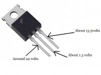
3. The regulator is happy with no load. Doubt a new one is bad, something is pulling the output down, that's why we have to isolate pin 4 of CN31 and measure on pin 3 of the reg (the output pin) to confirm all is well. The output should be around 13.3 volts or so due to the two series connected diodes on pin 2 of the reg adding to the 12 volt of the reg itself. If the voltage is OK you then follow the 13 volt rail and isolate all the low impedance feeds off it trying to split the thing in halves and quarters to narrow the area down.
2. I would not continue to recap without finding and fixing the fault first. Could the fault be "manmade" such as a solder blob or short somewhere. What readings do you get (with it all off) if you measure on ohms across the 13 volt rail from the output of the regulator.
3. The regulator is happy with no load. Doubt a new one is bad, something is pulling the output down, that's why we have to isolate pin 4 of CN31 and measure on pin 3 of the reg (the output pin) to confirm all is well. The output should be around 13.3 volts or so due to the two series connected diodes on pin 2 of the reg adding to the 12 volt of the reg itself. If the voltage is OK you then follow the 13 volt rail and isolate all the low impedance feeds off it trying to split the thing in halves and quarters to narrow the area down.
1. If the resistor has 28 volts across it (that is 28 on one end and zero on the other) then it is open circuit. Using a resistor like this is good for testing purposes rather than keep blowing fuses. You need some way of limiting the current though now... the bulb tester... so that you can work on "live" and see what's going on.
#1 - My mistake -there's 28.7V between either end of the resistor and ground.
2. I would not continue to recap without finding and fixing the fault first. Could the fault be "manmade" such as a solder blob or short somewhere. What readings do you get (with it all off) if you measure on ohms across the 13 volt rail from the output of the regulator.
#2 - There's no continuity ("1") for ohms at the regulator that was replaced. The tuner didn't work before I recapped the controller board and half the main board. (not my first recap- I've recapped a few receivers successfully so far, but I get what you mean about adding variables), and I just rechecked the main board and didn't find any solder bridges. From what I've read, this Nak was known for bad or cracked solder joints. I re-flowed the solder on any that looked suspect. Still no tuner, but the amp/preamp section works fine.
3. The regulator is happy with no load. Doubt a new one is bad, something is pulling the output down, that's why we have to isolate pin 4 of CN31 and measure on pin 3 of the reg (the output pin) to confirm all is well. The output should be around 13.3 volts or so due to the two series connected diodes on pin 2 of the reg adding to the 12 volt of the reg itself. If the voltage is OK you then follow the 13 volt rail and isolate all the low impedance feeds off it trying to split the thing in halves and quarters to narrow the area down.
#3 - Still working on this one.
Hope you're having a Happy Holiday!
Merry Christmas
1. 28 volts on both ends of 1 ohm resistor!
That's great, so looking at the circuit diagram you must also have 28 volts on pin 1 of the regulator itself ? That's the input pin.
Carefully measure the voltage on all 3 pins of the regulator itself, not on the board, on the reg... what do you get ?
1. 28 volts on both ends of 1 ohm resistor!
That's great, so looking at the circuit diagram you must also have 28 volts on pin 1 of the regulator itself ? That's the input pin.
Carefully measure the voltage on all 3 pins of the regulator itself, not on the board, on the reg... what do you get ?
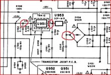
Here's the same image from a few posts back.
U953 (the fuse) has been replaced by a 1 ohm resistor... yes
You say there is 28 volts on each end of this 1 ohm resistor... yes ?
Pin 1 (the input pin) of the regulator has no voltage. All that's between the two is print and wire. The middle red circle.
U953 (the fuse) has been replaced by a 1 ohm resistor... yes
You say there is 28 volts on each end of this 1 ohm resistor... yes ?
Pin 1 (the input pin) of the regulator has no voltage. All that's between the two is print and wire. The middle red circle.
Attachments
Here's the same image from a few posts back.
U953 (the fuse) has been replaced by a 1 ohm resistor... yes
You say there is 28 volts on each end of this 1 ohm resistor... yes ?
YES - 28V
Pin 1 (the input pin) of the regulator has no voltage. All that's between the two is print and wire. The middle red circle.
I'm interpreting this as meaning the voltage between pin 1 of the regulator and one end of U953. I read 28V there, too.
There's no voltage between pin 1 of the reg and ground. Neither at the pin 1 of CR-41 (the left most circle), which is just a wire from the pin 1 of the Reg.
Regarding the righthand circle, I'm interpreting this to mean the voltages at the diode (Is this a diode bridge?). At the + leg, there's 14.52V. At the opposite corner leg there's 0.0V. The other two legs have 4.56V. All measured to ground.
Mooly - Thanks again for your time and patience.
From your readings and what you say it has to be a broken connection, but I can tell from your questions you are not really understanding what's going on.
You say there is 28 volts on the 1 ohm. That is the same point as the right hand red circle... and you mention 14.5 volts there.
Your readings don't really make sense tbh. Recheck carefully. All voltages are measured to ground. Yes the 4 diodes are a bridge.
With it turned off and with your meter on ohms (use the lowest ohms range) there should be continuity (a short) between pin 1 of the reg and the bridge rectifier (the four diodes) at the point where the red circle is. That point is also the positive end of the large cap C959. Check very carefully that the cap is connected OK, check that the print hasn't lifted and broken where the cap is soldered (check both connections of cap), and that there is continuity from this point all the way to the reg (via the 1 ohm). Make sure the negative end of the cap goes to ground and there are no breaks there.
Mooly,
You're assessment about understanding what's going on is correct. Also, I can't get to the bottom of the cap 959 without pulling the board out again. I should have put some leads on it the last time. This morning I tried to hook some wire under it to get a reading but was concerned about making a short.
I'll get the board out in the next day or so and recheck everything. I did notice that the pads seemed very fragile all over this unit. Not the type of quality I would expect from vintage Nak. Same for most of the no-name caps I found, with the exception of the Nichicon Muse I left in.
You're assessment about understanding what's going on is correct.
Also, I can't get to the bottom of the cap 959 without pulling the board out again. I should have put some leads on it the last time. This morning I tried to hook some wire under it to get a reading but was concerned about making a short.I'll get the board out in the next day or so and recheck everything. I did notice that the pads seemed very fragile all over this unit. Not the type of quality I would expect from vintage Nak. Same for most of the no-name caps I found, with the exception of the Nichicon Muse I left in.
Progress! Sort of....
I just might use up the entire supply of sheepish grins. As it turns out, I replaced U952 fuse instead of U953. I discovered it when testing for continuity between the diode and with
C959 (which was fine). So now fuse U953 has been replaced with a 1 ohm resistor, too).
OK, so that being done - still no FM, but here are the voltages:
Between Reg Pin 1 and CN41 ( pin 1 of connector cable):22V
Between Ground and Reg Pin1 - 0.0V
Between 1 end of fuse (U953) and ground: 23V
Between other end of (U953) and ground: 0.0 V
Between either end of U952 and ground: 47V (?)
There was continuity between the pos of C962 and pos of diode D956.
Is it correct that there's no voltage between ground and any of the Reg pins? There's voltage from Pin1 of CN41 (left hand circle) to each of the pins on the Reg (22.2V, 22.7V, 23.4V.)
Pin 4 of CN31 has less than 1V.
The control panel seems to work (except for the tuner) and the cd input plays fine both channels.
I await further instructions! Thanks again!
Last edited:
Hmmm Lets start again lol
OK then... U953 with 22 volts on one end and zero on the other is blown.
And you have a 1 ohm fitted for U953. So that is open circuit (blown).
You need to confirm the supply is OK first.
1. Replace the 1 ohm (U953)
2. Disconnect the output wire from the reg to the main board and then power up and check 13 volts is OK on the reg itself.
This is what you should see,
Lets start again lolOK then... U953 with 22 volts on one end and zero on the other is blown.
And you have a 1 ohm fitted for U953. So that is open circuit (blown).
You need to confirm the supply is OK first.
1. Replace the 1 ohm (U953)
2. Disconnect the output wire from the reg to the main board and then power up and check 13 volts is OK on the reg itself.
This is what you should see,
Attachments
You have no voltage at all on the reg yet have 23 volts on U953 ?
Look at the circuit
U953 goes directly to the reg... it's just wire and print.
Are you sure you are getting a good connection with the meter leads on the reg ? Any solder flux acts as an insulator. That 23 volts should be on the "left" pin of the reg, the one I marked as "around 22 volts" in the picture above. Be careful measuring as one slip shorting that pin to the middle would damage the two diodes connected there.
There is a 3-wire flat cable connecting the reg to the controller board. I removed the wire, folded down the rightmost wire corresponding to the right leg of the reg and taped it overbefore reinstalling it. Perhaps this is not what you meant by isolating it. But if I remove the cable completely - then the reg is disconnected.
The diode bridge adjacent to C959 reads 23.4V at the +, 0.0V at the opposite corner and 7.6V at each of the other two legs. Is that the diode that you were concerned about being damaged?
The diode bridge adjacent to C959 reads 23.4V at the +, 0.0V at the opposite corner and 7.6V at each of the other two legs. Is that the diode that you were concerned about being damaged?
Is this giving you sleepless nights
That's fine, so you have the left and middle pin connected on the reg.
That's good... now that 23 volts has got to appear at the left pin on the reg. Do you see ? It's a direct connection via U953.
The right hand (output) lead of the reg should have 13.5 or so volts on it even though it is not connected.
The diodes I meant were the two connected in series from the middle leg of the reg to ground.
There is a 3-wire flat cable connecting the reg to the controller board. I removed the wire, folded down the rightmost wire corresponding to the right leg of the reg and taped it overbefore reinstalling it. Perhaps this is not what you meant by isolating it.
That's fine, so you have the left and middle pin connected on the reg.
The diode bridge adjacent to C959 reads 23.4V at the +, 0.0V at the opposite corner. and 7.6V at each of the other two legs. Is that the diode that you were concerned about being damaged?
That's good... now that 23 volts has got to appear at the left pin on the reg. Do you see ? It's a direct connection via U953.
The right hand (output) lead of the reg should have 13.5 or so volts on it even though it is not connected.
The diodes I meant were the two connected in series from the middle leg of the reg to ground.
- Status
- This old topic is closed. If you want to reopen this topic, contact a moderator using the "Report Post" button.
- Home
- Source & Line
- Analog Line Level
- Nakamichi TA4A tuner has no output