That voltage drop is the difference between total Vf of a LEDs tripplet and their neighboring MOSFET's Vgs. As the current setting will be made stronger the drop will be lower because of the MOSFETS Vgs growing with higher current. Use green LEDS triplet for more voltage drop on the setting resistors when you want more current with a given Ohmic value of those. Green LEDS have higher VF than REDS.
OK...so I took a voltage measurement on both legs of the 5 Ohm 3.75 Watt current setting resistors that are installed by placing the DMM negative probe on the Vout ground pad and clamping the positive probe on both legs of each resistor.
My results were -19.7/-18.2 and 19.6/18.12. That puts the voltage drops at 1.48 and 1.5. With a 5 Ohm resistor in place the math says .296 A and .3 A or 296 mA and 300 mA. So my hot rodding is more like luke warming.
I suppose I could try the 3 Ohm 3.75 Watt resistors that came with my kit and see where that puts me.
By the way...the measurement I took off the transformer secondaries into the power header of the board was incorrect. I was using an older DMM and discovered it is not working properly when I retested the secondary voltage with my known to be accurate newer RMS DMM. The secondaries of the Antek 0515 transformer are actually putting out 15.25 VAC as opposed to the 12.4 VAC I measured with the old meter.
I rechecked all other measurements after an hour or two of idling and they all remained essentially the same.
Is there anything about my Vout voltages being lower than normal and the positive rail not having a slightly higher voltage that is to be concerned about or that is influencing the current setting process?
Simply probing across the legs of the resistor (red to input leg black to output leg for a correct sign) will read its voltage drop directly. Anyways, the result will be the same as with the way you derived it.
There's nothing much about Vout voltages being bit lower or bit higher than in other builders reports, its a matter of parts characteristics and tolerances (LEDS VF, JFETS IDSS). Positive rail anticipated higher enough than the negative was an inherent characteristic of the classic Mezmerize board only (neither expected in the Hypnotize legacy board nor in the Ten Years After commemorative Mezmerize issue currently offered by the DIYA store).
There's nothing much about Vout voltages being bit lower or bit higher than in other builders reports, its a matter of parts characteristics and tolerances (LEDS VF, JFETS IDSS). Positive rail anticipated higher enough than the negative was an inherent characteristic of the classic Mezmerize board only (neither expected in the Hypnotize legacy board nor in the Ten Years After commemorative Mezmerize issue currently offered by the DIYA store).
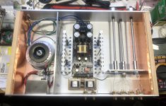
Finished modifications to my DCB1 based preamp. Now its an Iron-Hypo ")
Jensen’s are tucked in the back in series with the outputs. Hopefully the 6dB of gain will help make my phono happier sounding.
I replaced the pots with some proper logarithmic NOS Clarostat units which I bought of off eBay. I matched them for the highest impedance I could find out of 100 I had. My phono has an output impedance approaching 3K, so I figured any help I could find avoiding a mismatch problem I should take advantage of.
I cleaned up and shortened the input signal wiring.
Added the new safe ground that connects the circuit board’s central ground to the chassis and lifts it to help with any ground loop issues.
I had to pull my fancy TX2575 series output resistors in order for the buffer to be able to drive the transformers, but the remaining other important resistors are all the same or similar quality.
I adjusted the current setting resistors in the power supply to run it at higher current to see if it will give me some sonic benefits like improved sound stage and blah blah.
I was running it pretty cool and only increased it to about 300mA. Still not much heat generated, but I had the lid off and have been running it like that since I finished it a couple years ago.
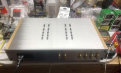
I finished the top cover with ventilation for the transistor heat sinks finally and put it in place. I’ll have to fire it up again and monitor the heat build up for a while. Hopefully it won’t be an issue as the entire core of the chassis is 1/8” aluminum plate and acts as an additional heat sink to the ones I made and installed. My preliminary tests only showed about 105 degrees F on the transistor hardware after an hour or so at idle.
Offset actually dropped to -1.2 mV on both channels after I finalized all wiring. Vout +/- is at 9.6V on both channels.
Hope to fire it back up later and make sure the offset and heat still seems fine.
Jensen’s are tucked in the back in series with the outputs. Hopefully the 6dB of gain will help make my phono happier sounding.
I replaced the pots with some proper logarithmic NOS Clarostat units which I bought of off eBay. I matched them for the highest impedance I could find out of 100 I had. My phono has an output impedance approaching 3K, so I figured any help I could find avoiding a mismatch problem I should take advantage of.
I cleaned up and shortened the input signal wiring.
Added the new safe ground that connects the circuit board’s central ground to the chassis and lifts it to help with any ground loop issues.
I had to pull my fancy TX2575 series output resistors in order for the buffer to be able to drive the transformers, but the remaining other important resistors are all the same or similar quality.
I adjusted the current setting resistors in the power supply to run it at higher current to see if it will give me some sonic benefits like improved sound stage and blah blah.
I was running it pretty cool and only increased it to about 300mA. Still not much heat generated, but I had the lid off and have been running it like that since I finished it a couple years ago.
I finished the top cover with ventilation for the transistor heat sinks finally and put it in place. I’ll have to fire it up again and monitor the heat build up for a while. Hopefully it won’t be an issue as the entire core of the chassis is 1/8” aluminum plate and acts as an additional heat sink to the ones I made and installed. My preliminary tests only showed about 105 degrees F on the transistor hardware after an hour or so at idle.
Offset actually dropped to -1.2 mV on both channels after I finalized all wiring. Vout +/- is at 9.6V on both channels.
Hope to fire it back up later and make sure the offset and heat still seems fine.
Attachments
That's a very neat build. Congrats. I don't think you will have any heat or offset problems with the top on after using so much metal there. With a 3k Zo source your pots should be at least 30k nominal. Do you have means to check that the frequency response and THD remain good or there's no square wave ringing after the inclusion of the Jensen transformers?
I only had time to put the cover in place this weekend and monitor the temperature at the transistor hardware for an hour or so at idle. It didn’t even get over 100 degrees F. No change in DC offset. I just need to put a protective coat of wax on the raw aluminum cover before I hook things up for a listen.
I realize that the 3K Zo of my phono amp is a less than ideal match to the 20K pots I decided to continue using. We had discussed this issue back in November of 2015 when I was first building this preamp on page 523. AndrewT also gave his opinion concerning impedance matching.
I wanted to use what I had on hand to try and get rid of the linear Noble pots that weren’t working well. The Nobles seemed to be one of the biggest disappointments in the preamp. I have a set of 50K Alps pots on hand, but they were reserved for my tube preamp which has become a sort of benchmark for me to best with my DIY SS projects. I also did not have a decent 680K resistor on hand to use with them in the DCB1. So, with the Clarostat 20K log pots having at least 6X the Zo of the phono amp I decided to compromise. It’s only a temporary one at most as I already have a complete Simplistic NJFET RIAA kit that is waiting to be built.
I’ve only just begun exploring testing in any form with my system. I have a UMIK and I have REW software functioning on my laptop. I have successfully done some in room frequency sweeps and measurement to help with setting up the B5 I am using for crossover duties in my system. REW has the ability to generate Sine Waves as well.
The only tool I have to analyze any signals I would generate and send through the preamp is a DSO Nano pocket oscilloscope that I got for free with a bunch of parts I bought from a member in the swap meet. It works, but is an older version and the support and instruction I have found so far related to its use has not helped me in any way overcome the fact that I have no training or experience what so ever in how to use an oscilloscope let alone interpret a square wave I might generate with it.
The transformers were the simplest way to try and get some more gain which was obviously lacking in my system while trying to use my phono source. All I can do at this point is listen and see if things are better to my ears.
Last edited:
You can FFT and FR with REW and a sound card/external interface. There's a learning curve on the concept, the software, and the card's calibration, but not too steep. Time consuming mainly. Digital audio interfaces are no good for square waves though, since they produce much ringing of their own. Meantime, let us know your subjective results.
That same question had spawned a thread in 2009. Enjoy: Using the HYPNOTIZE as a general shunt reg PCB
P.S. In later issue double layer blue or black Hypno and in Ten Years After current issue Mezmerize you don't need to perform the leg trick (i.e. no need to join G+S of one K170 as in the link's first post/first picture)
P.S. In later issue double layer blue or black Hypno and in Ten Years After current issue Mezmerize you don't need to perform the leg trick (i.e. no need to join G+S of one K170 as in the link's first post/first picture)
My Iron-Hypo project appears to be successful.
There were no issues with heat or DC offset at all.
I’ve had over a week to listen to it now.
In my initial eagerness to test it I had a less than ideal first experience. Part of it was that there was much distraction on the weekend going on about the house.
The first test was with my phono source. Honestly, it left me scratching my head and walking away a bit frustrated. I wasn’t sure things didn’t sound worse.
When I came back to the system a few days later I listened to it enough to evaluate how much more gain I appeared to have at my disposal.
The CD player had way more gain than it needed. Luckily, the NEC unit I had started using because my old Rotel died has a built in output level pot and I was able to dial it back to the middle of its range so that it seemed to work well with the preamp.
Sometimes I like to be lazy and just stream background music from my iPad. The sound quality is mediocre at best, but is fine for cooking a meal to.
The iPad wasn’t able to match the dynamics of the CD player...maybe because it wasn’t able to produce as powerful an output signal in addition to the lower quality signal. Now it is capable of much more and also seems a good match for the preamp.
I had decided to give the phono another shot and turned my head amp and phono amp on to warm up for a little while while I listened to the digital sources.
Both my head amp and phono amp run on hi capacity NiMH battery packs that I sourced online. I installed voltage meters in them that are set up with a test switch so I can check the battery’s level for the amps before using them.
Well, when I tested the head amp I noticed the voltage had dropped down around 9.8 V, and as I was watching continued to drift down. After almost a year since I had installed it’s battery pack it appeared to finally need charging.
Recharging the head amp battery finally gave me more of the results that I was after. The phono is now able to drive the system to much higher levels. The bass it produces with the slot loaded dipole bass units I just finished is wonderful.
The only issue I have is that in my enthusiasm of finally being able to rock the house with the Black Keys from my phono source I reached a level on the volume control around 2:00 or so where the system seems to start producing uncontrollable lower frequency feedback through the speakers. Granted, everyone else in the house was already complaining about the level when the volume was at 12:00
The audible feedback subsides if I dial the volume back to about 1:00. I’ve not experienced this before, and I have blasted quite a few albums on my parents old Pioneer receiver as a teenager.
I looked into the issue briefly and realized that even though I’ve never personally experienced feedback like this that the issue has always existed. It seems that I may have to take a look at trying to relocate and isolate my turntable a bit better if I want to continue with “enthusiastic” listening sessions. If the problem is actually the cartridge stylus experiencing uncontrollable oscillation in the groove I may need to revisit my tonearm setup.
I tried a few other albums and it does not seem related to the specific recording as regardless to the nature of the material (Jazz, Blues, Acoustic) the same noise occurs once I reach that level in the volume control.
I also compared recordings that I have of the same material on LP and CD which are created from the same masters to evaluate and compare the sonics of the CD versus the phono source.
I was particularly interested in the impression of the bass response. I looked into the subject of square wave ringing, which is not a subject I was familiar with. My brief look into information I could find on the subject said that square wave ringing and how it may affect the audible range varies by opinion but that it may have an affect on the lower frequency range?
As I mentioned, the overall bass response of the system in general was very satisfying. It is supplemented below 75Hz with a subwoofer. I will say that the CD source of the recordings I compared did seem to have a slight advantage in the area of bass response, but it was not necessarily any better. I found there to be slightly more bass, but the bass gave me the impression of a bloated boomy bottom end.
Now I am just trying to spend more time listening to and enjoying music and trying to form a more detailed impression of the system.
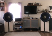
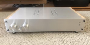
Below is a bit of a lousy picture from my phone made worse due to the light from the window behind. Also a pic of the preamp all buttoned up with a new lid and ready to play.
I have Lowther DX3s in the Oris Horns being driven by the humble little ACAs I built with some Semisouth slipped into Q1.
The dipole bass units are loaded with 6 each of those buyout 8” Peerless that Papa came across at Parts Express shortly after he produced the SLOB article. Some old bridged Rotel AV amps drive them.
Signals are managed by a B5.
There were no issues with heat or DC offset at all.
I’ve had over a week to listen to it now.
In my initial eagerness to test it I had a less than ideal first experience. Part of it was that there was much distraction on the weekend going on about the house.
The first test was with my phono source. Honestly, it left me scratching my head and walking away a bit frustrated. I wasn’t sure things didn’t sound worse.
When I came back to the system a few days later I listened to it enough to evaluate how much more gain I appeared to have at my disposal.
The CD player had way more gain than it needed. Luckily, the NEC unit I had started using because my old Rotel died has a built in output level pot and I was able to dial it back to the middle of its range so that it seemed to work well with the preamp.
Sometimes I like to be lazy and just stream background music from my iPad. The sound quality is mediocre at best, but is fine for cooking a meal to.
The iPad wasn’t able to match the dynamics of the CD player...maybe because it wasn’t able to produce as powerful an output signal in addition to the lower quality signal. Now it is capable of much more and also seems a good match for the preamp.
I had decided to give the phono another shot and turned my head amp and phono amp on to warm up for a little while while I listened to the digital sources.
Both my head amp and phono amp run on hi capacity NiMH battery packs that I sourced online. I installed voltage meters in them that are set up with a test switch so I can check the battery’s level for the amps before using them.
Well, when I tested the head amp I noticed the voltage had dropped down around 9.8 V, and as I was watching continued to drift down. After almost a year since I had installed it’s battery pack it appeared to finally need charging.
Recharging the head amp battery finally gave me more of the results that I was after. The phono is now able to drive the system to much higher levels. The bass it produces with the slot loaded dipole bass units I just finished is wonderful.
The only issue I have is that in my enthusiasm of finally being able to rock the house with the Black Keys from my phono source I reached a level on the volume control around 2:00 or so where the system seems to start producing uncontrollable lower frequency feedback through the speakers. Granted, everyone else in the house was already complaining about the level when the volume was at 12:00
The audible feedback subsides if I dial the volume back to about 1:00. I’ve not experienced this before, and I have blasted quite a few albums on my parents old Pioneer receiver as a teenager.
I looked into the issue briefly and realized that even though I’ve never personally experienced feedback like this that the issue has always existed. It seems that I may have to take a look at trying to relocate and isolate my turntable a bit better if I want to continue with “enthusiastic” listening sessions. If the problem is actually the cartridge stylus experiencing uncontrollable oscillation in the groove I may need to revisit my tonearm setup.
I tried a few other albums and it does not seem related to the specific recording as regardless to the nature of the material (Jazz, Blues, Acoustic) the same noise occurs once I reach that level in the volume control.
I also compared recordings that I have of the same material on LP and CD which are created from the same masters to evaluate and compare the sonics of the CD versus the phono source.
I was particularly interested in the impression of the bass response. I looked into the subject of square wave ringing, which is not a subject I was familiar with. My brief look into information I could find on the subject said that square wave ringing and how it may affect the audible range varies by opinion but that it may have an affect on the lower frequency range?
As I mentioned, the overall bass response of the system in general was very satisfying. It is supplemented below 75Hz with a subwoofer. I will say that the CD source of the recordings I compared did seem to have a slight advantage in the area of bass response, but it was not necessarily any better. I found there to be slightly more bass, but the bass gave me the impression of a bloated boomy bottom end.
Now I am just trying to spend more time listening to and enjoying music and trying to form a more detailed impression of the system.
Below is a bit of a lousy picture from my phone made worse due to the light from the window behind. Also a pic of the preamp all buttoned up with a new lid and ready to play.
I have Lowther DX3s in the Oris Horns being driven by the humble little ACAs I built with some Semisouth slipped into Q1.
The dipole bass units are loaded with 6 each of those buyout 8” Peerless that Papa came across at Parts Express shortly after he produced the SLOB article. Some old bridged Rotel AV amps drive them.
Signals are managed by a B5.
Attachments
My brief look into information I could find on the subject said that square wave ringing and how it may affect the audible range varies by opinion but that it may have an affect on the lower frequency range?
No it wouldn't. Ringing could make the highs brilliant and/or harsh. Bass control would have more to do with successfully driving the transformer you added at the buffer preamp's output and how it drives the various power amps on its own right.
Thanks for clarifying those two issues for me. I had trouble finding any information that gave an explanation about the ringing issue and how it related to what one would hear in layman’s terms.
I guessed that I was misunderstanding the information I found and your explanation seems perfectly logical in hindsight.
Subjectively, I would say that if there are high frequency issues due to ringing or bass control issues relating to the load of the transformer on the buffer or the transformer driving my amps they are not presenting themselves in a manner that is audibly distracting to me.
I am using the baffle step filter in the B5 to tame the Lowthers a little so that they aren’t irritating me with shrill resonances. The filter had been previously set at 2dB down starting at around 1 or 2.5K. I didn’t experience any additional uncomfortable resonance or distortion in this frequency range or above while playing familiar recordings that I had made these adjustments with originally.
The bass, as I previously mentioned, was very satisfying and seemed to have good clarity.
Finished modifications to my DCB1 based preamp. Now its an Iron-Hypo
Jensen’s are tucked in the back in series with the outputs. Hopefully the 6dB of gain will help make my phono happier sounding.
I replaced the pots with some proper logarithmic NOS Clarostat units which I bought of off eBay. I matched them for the highest impedance I could find out of 100 I had. My phono has an output impedance approaching 3K, so I figured any help I could find avoiding a mismatch problem I should take advantage of.
I cleaned up and shortened the input signal wiring.
Added the new safe ground that connects the circuit board’s central ground to the chassis and lifts it to help with any ground loop issues.
I had to pull my fancy TX2575 series output resistors in order for the buffer to be able to drive the transformers, but the remaining other important resistors are all the same or similar quality.
I adjusted the current setting resistors in the power supply to run it at higher current to see if it will give me some sonic benefits like improved sound stage and blah blah.
I was running it pretty cool and only increased it to about 300mA. Still not much heat generated, but I had the lid off and have been running it like that since I finished it a couple years ago.
I finished the top cover with ventilation for the transistor heat sinks finally and put it in place. I’ll have to fire it up again and monitor the heat build up for a while. Hopefully it won’t be an issue as the entire core of the chassis is 1/8” aluminum plate and acts as an additional heat sink to the ones I made and installed. My preliminary tests only showed about 105 degrees F on the transistor hardware after an hour or so at idle.
Offset actually dropped to -1.2 mV on both channels after I finalized all wiring. Vout +/- is at 9.6V on both channels.
Hope to fire it back up later and make sure the offset and heat still seems fine.
Just saw the pic of the amp. Do you go from the input jacks to the pot directly? I think this is a bad idea. You need an impedance transformation!
I’m thinking of pushing the boat out and ordering a Khozmo attenuator for my DCB1. In theory I like the idea of the shunt version, as there’s only two resistors in the signal path.
Khozmo Stereo Shunt Stepped Attenuator, 48 step MKII | Hifi Collective
But I thought I’d best check which version is best for DCB1, the 20K shunt or the series version? Or is there little difference?
Cheers,
John.
Khozmo Stereo Shunt Stepped Attenuator, 48 step MKII | Hifi Collective
But I thought I’d best check which version is best for DCB1, the 20K shunt or the series version? Or is there little difference?
Cheers,
John.
- Home
- Source & Line
- Analog Line Level
- Salas hotrodded blue DCB1 build