Help with Grouping of K170BL
Hi Salas,
I am building a pair of DCB1 (blue) boards for use as a balanced preamp, and I have measured (IDSS only) 20 pieces of K170BL. It's likely that I will 'hotrod' the circuits.
It looks like there are some decent quads in this set, but it doesn't look as though I will be able to have the same IDSS grouping between channels (but probably close enough).
My IDSS measurements are:
a - 8.07 b - 8.08 c - 8.11 d - 8.14 e - 8.23
f - 8.23 g - 8.24 h - 8.29 i - 8.35 j - 8.39
k - 8.39 l - 8.42 m - 8.68 n - 8.69 o - 8.69
p - 8.70 q - 8.84 r - 8.86 s - 8.88 t - 8.89
For the buffer sections I was thinking of using m-n-o-p for one channel and q-r-s-t for the other. I could probably use lower IDSS groups in the buffer if there is an advantage to that.
Can you please offer comments as to higher vs lower IDSS, or if you can see better groups in this set I would appreciate your guidance.
ps I've read about placement of the "inner pairs" in the buffer section that is discussed in other posts.
Thanks,
-Keith-
Use closer together individual pairs per channel than worrying for closeness between channels (or phases) since all listed samples above are already within 1 mA vicinity. The THD will be close enough between channels (or phases) because transconductance is not far away yet for 1mA. But you will see offset differences with every mA fraction of IDSS mismatch in a pair.
Bit weird to find so many close ones in twenty though. Is there a close up picture of your K170BL you can post? To exclude any possibility they are fakes before you proceed. A mobile phone clean shot will do.
Oh, it wasn’t 20 random jets, this was from Spencer, which I acquired much earlier this year. I requested 2 matched quads inthe 8-9 mA range (viz. an octet) and 4 other quads in the 8-9 mA range. My measurements don’t correspond directly with his, but I was using just a simple 9v jig with my dmm. Certainly can post pics tomorrow.
Coming from Spencer explains the closeness. When you measure IDSS don't handle them with your fingers, use a tool. Also make sure you note down the readings for the same time length. Say two minutes for each one after you applied the battery. Because they drift upwards as they warm up. Spencer's DMM and your DMM may also have different burden voltage when using them in series mA mode. When using the small value resistor voltage drop method its only down to meters DC accuracy in mV scale.
I ran the tests in series current mode until stable for 1 minute - probably excessive but I have noticed the IDSS drift as the fets warm up. I also think that Spencer's home is relatively warm compared to my house.
It might be interesting to repeat the tests with a series resistor - I think my dmm is good to +/-0.1 mV (would have to check that).
Thanks again Salas, I'll update as the build progresses, although my DCG3 should be completed first.
It might be interesting to repeat the tests with a series resistor - I think my dmm is good to +/-0.1 mV (would have to check that).
Thanks again Salas, I'll update as the build progresses, although my DCG3 should be completed first.
Oh, it wasn’t 20 random jets, this was from Spencer, which I acquired much earlier this year. I requested 2 matched quads inthe 8-9 mA range (viz. an octet) and 4 other quads in the 8-9 mA range. My measurements don’t correspond directly with his, but I was using just a simple 9v jig with my dmm. Certainly can post pics tomorrow.
Do you have a link to Spencer?
Thanks,
-Josh
Do you have a link to Spencer?
Thanks,
-Josh
Hey Josh,
Here you are: FET Audio | Hi-End Audio Projects
There are other sellers who are generally regarded as having genuine toshiba fets such as "punkydawgs" on ebay (although his prices have increased quite a bit).
Be careful on ebay though, many counterfeits.
You could also get Linear Systems pieces from the DIYAudio Store but they are frequently sold out.
-K-
Thanks for getting back so fast.
I ordered the board from the DIYStore last night, the store is out of jfets though.
So, an interesting question (that has probably been answered someplace inside the 1000+ pages of thread that are scattered about the forum on this preamp.
If I source a nice set of matched Toshiba (or even Linear Systems), can I use random jfets from any (quality) brand, or do I need to stick to matching brands for the un-matched ones? Adding 6 more Toshiba's will drive the cost way up.
Also, has anyone done a semi-recent build thread on this? The threads are so long, that good info will easily get missed trying to read all of them.
@joshua43214
Ask Spencer for six pieces 6-8mA Toshiba 2SK170BL non matched. He will surely have many leftovers from matching processes. This is the old Hypnotize hot-rod thread. The most modern and short one for Mezmerize is the store's thread. Has an updated BOM with tips there also.
Ask Spencer for six pieces 6-8mA Toshiba 2SK170BL non matched. He will surely have many leftovers from matching processes. This is the old Hypnotize hot-rod thread. The most modern and short one for Mezmerize is the store's thread. Has an updated BOM with tips there also.
@Salas
Thanks, I sent him an email, expect he will see it when his time zone rolls around.
I did actually start reading the thread from the store, then followed the links to this thread, and the old Mesmerize thread, then got sidetracked on the topic of attenuators, then DC protection circuits, and then...
I expect it will go well, the BOM is nicely done. I expect it will be easier to puzzle out than the M2x I just completed. Part of me is fine with the project dragging on a bit. I still have not been able to have a good critical listening session with the M2x and decide which input board is the best. Every time I sit down to listen to it, I end up just enjoying the music")
But then again, that is the whole point...
Thanks, I sent him an email, expect he will see it when his time zone rolls around.
I did actually start reading the thread from the store, then followed the links to this thread, and the old Mesmerize thread, then got sidetracked on the topic of attenuators, then DC protection circuits, and then...
I expect it will go well, the BOM is nicely done. I expect it will be easier to puzzle out than the M2x I just completed. Part of me is fine with the project dragging on a bit. I still have not been able to have a good critical listening session with the M2x and decide which input board is the best. Every time I sit down to listen to it, I end up just enjoying the music
But then again, that is the whole point...
The DCB1 has been built successfully so many times by so many different people of different skills during a decade's span that's almost impossible you have any serious chance of not being able to finish it or to totally subjectively disappoint you given that the amp and the speakers have the sensitivity for a unity gain control buffer to give you enough volume. In the store's thread I had also posted more alternative sources than Spencer (answer #242).
I finished my build in 2012 (with Tea-Bag's kit & 10R), but I seemed to have some sound quality issue so I have not used it often. I would appreciate hints to help me get back on it.
My current listening setup is: USB source => DAC (Audio-GD Ref-7) => Aleph 3 => speaker (Philharmonitor) in a very small (10'x10') room. Volume is controlled by the software Foobar2000 (usually software volume is about -30dB). I listen mostly soundtracks and classical. Sound is neutral, clean, and very well defined stage.
When I added DCB1 in chain, the sound seems to be warmed up (with more harmonics?), but the stage becomes smaller toward center. The problem that bothers me most is the edges of sound being smoothed throughout the high/mid/bass. The beginning edge of each note (piano or percussion) is rounded and less well defined. Bass is less solid and impact. I am not a bass-head but do appreciate well-defined bass.
I am a newbie in building and choosing components. I wonder if some of my components or volume pot may be the source of problem? Thanks a lot for a pointer to start debugging.
Hi everybody,
I got 2 boards from Teabag and I am thinking of a balanced version.
3 questions here:
1. Can I use the Vout terminal beside J2 to simultaneously power the IC-based volume control unit? It says 9-15Vdc is ok.
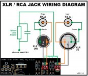
2. I did a diagram of my understanding of how to wire RCA-Balanced mode.(I am a visual person) Is that correct? Do I need to put a resistor somewhere or need a switch?
3. Is the signal ground connected to the ground loop breaker correct?
Thanks for the help!
I got 2 boards from Teabag and I am thinking of a balanced version.
3 questions here:
1. Can I use the Vout terminal beside J2 to simultaneously power the IC-based volume control unit? It says 9-15Vdc is ok.
2. I did a diagram of my understanding of how to wire RCA-Balanced mode.(I am a visual person) Is that correct? Do I need to put a resistor somewhere or need a switch?
3. Is the signal ground connected to the ground loop breaker correct?
Thanks for the help!
Attachments
1. Yes, but the IC volume controller's consumption must either be low enough thus negligible, or account for it as extra loading in the positive PSU section's CCS setting. So to end up with same extra shunted current in both rails sections.
2. Looks good to me for XLR but for the RCA there must also be direct connection between its barrel and signal ground first because there is no return path now except through the breaker.
3. When for XLR only, yes.
2. Looks good to me for XLR but for the RCA there must also be direct connection between its barrel and signal ground first because there is no return path now except through the breaker.
3. When for XLR only, yes.
1. Yes, but the IC volume controller's consumption must either be low enough thus negligible, or account for it as extra loading in the positive PSU section's CCS setting. So to end up with same extra shunted current in both rails sections.
2. Looks good to me for XLR but for the RCA there must also be direct connection between its barrel and signal ground first because there is no return path now except through the breaker.
3. When for XLR only, yes.
Thanks Salas for the quick reply.
The IC based volume control needs only +/- 22mA.
I think the value is insignificant...?
I will make a wire connection from RCA barrel to signal ground.
22mA extra loading will not starve the shunt regs, far from that, but better use 8.2R 5W CCS setting resistors in the shunt PSU sections to compensate against the extra loading so to have about the same spare current as other builders with 10R but with no extra loads.
Yes, first connect signal return to the RCA barrels, then break it to chassis. The RCAs must be insulated to chassis so to route as you like.
Yes, first connect signal return to the RCA barrels, then break it to chassis. The RCAs must be insulated to chassis so to route as you like.
- Home
- Source & Line
- Analog Line Level
- Salas hotrodded blue DCB1 build