Hi all,
I was quite happy with my dcb1 listening for a month and over very excellent sound quality.... but now something bad is happening!
Occasionally, after some hours of power on one of the Leds string (the one on the IRFP9240 side) switch off...and quite soon they switch on again....and everything is fine again...
Of course in the middle of this switch off/on sound is distorted and noisy
Soldering is ok. I double checked.
May be too much heat? (is quite warm now-days in Italy)
Suggestion on what I can check?
Tanks,
Saveerio
Some intermittent LED in the string?
No, no.
All five LEDS switch off at same time and then after 1-2 secs they switch on again!...
(may be useful to say that last modification was adding a blue led (on the proper place) and tapping off the bridge (from the power caps) the voltage for an extra (out of the board) LM7809 intended to power a little fan (but actually still disconnected from the fan!)
If only one is switching then all will do because in series like chain links. There is a K170 sinking them to ground. That one can be suspicious also. I would change all 5 LEDS and the K170 if I could not focus on one intermittent component or one cold joint. I would also inspect the board vias and Mosfet joints because maybe little cracked when bolting the Mosfets to sink. Rework the joints for sure.
High offset on one channel, help
Hi
I just finished the DCB1 Black board (Tea bag kit) and I have a problem with the left channel offset at -85mv. Right is 2.3mv.
Vout is 9.94v and -9.95v. Voltage across the 10r is 1.8v on both channels.
Does the high dc offset mean the fets on the left channel are not closely matched? should l replace them?
Thank you
KJ
Hi Salas, yes, the board looks ok ")
I went ahead and removed the pair on the right channel and replaced it with a decently matched 2sk170 I had from a previous projects. The offset is now 3.5mv yay ... but now I have 2 kinds of fets (2sk170 for the right 3.5mv offset and LSK170 for the left -0.7mv offset) is this ok?
P.S. The 2sk170 have an idss around 7ma while the lsk170 are around 11ma
Thank you
KJ
I went ahead and removed the pair on the right channel and replaced it with a decently matched 2sk170 I had from a previous projects. The offset is now 3.5mv yay
... but now I have 2 kinds of fets (2sk170 for the right 3.5mv offset and LSK170 for the left -0.7mv offset) is this ok?P.S. The 2sk170 have an idss around 7ma while the lsk170 are around 11ma
Thank you
KJ
Last edited:
Its OK for now and the THD channel differences can be small but for residents I would prefer two well matched elements pairs from same brand not far than 1mA IDSS distance between pairs. Ask Tea to help finding another good pair of 10-11-12mA LSK or 6-7-8mA SK to symmetrically fit there. Watch it with the iron. Not too long.
Ok, new fets ordered from Tea Bag. I tried the buffer with 2sk and lsk. Sounds good. I noticed that there is a 10c difference in temp between the irfp420 and 9420 (25-30 to 35-40 respectively), is this normal?
Thanks
kj
They both have same 0.83C/W RθJC. So to have thermal differences you must have different current between positive and negative psu sections or some bolting and sinking is not done as good as in the other section. You wrote you got 1.8V across each 10 Ohm setting resistor, that translates to 180mA in each polarity. The relay circuit reliefs the positive bank output by a tiny further 10mA than the negative that only feed the JFETS. Maybe enough to extinguish the positive side LEDS bit faster at power off. Not enough to drop VinDC asymmetrically. So check if there is more AC input voltage to one side and the mounting quality, thermal paste, etc.
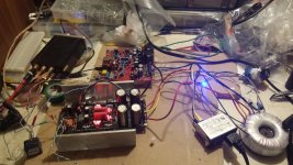
I remeasured across the 10r while playing music. The hot side is 1.87 vdrop, the other is 1.81v. Can this explain it? I will re check the sinking too. Thanks Salas. The buffer sounds really good, but you already know that lol
BTW here is a picture of my test setup
kj
BTW here is a picture of my test setup
kj
Attachments
Last edited:
No, the current draw differences are minimal in your case so to explain 10C worth difference of dissipation in such heavy MOSFETS. Measure your secondaries ACV between center bolt and side bolts on the AC input connector on the PCB. Are they the same? If the input voltages, the CCS currents, and the output voltages are roughly the same between polarities, the dissipations are the same. Then it points to mounting and sinking thermal efficiency. A rougher Alu surface, a less than optimum tightening, or efficient and inefficient Silpads mix can give differences. Also if using a laser pointing thermometer gun, it can grossly mislead you if not able to correct coefficient for shiny surfaces mixed reflections. Are one side MOSFETs surely hotter when touching each one with your finger or a K probe wire?
 (The posts had to be moved here because this is a Hypnotize Hot-Rod board you got, not a Mezmerize).
- Home
- Source & Line
- Analog Line Level
- Salas hotrodded blue DCB1 build