Hi Guys.
I am trying to put together a plan for a preamp I want to build in the near future. I require 2 stereo line level inputs and another input which caters for 5.1 (6) channels to connect to my PC. I have put together a little block diagram schematic of how I think I can implement this design relatively easily, but I have made some assumptions which I would like validated.
Firstly I will talk you though my design. I am adapting the design from High Quality Audio Preamp
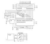
If PC input is selected, the 6 op amps in the inital +6dB amplifier section are powered on (the ones with the small '3' on them). These 6 channels get passed straight through into the second amplifier stage, and then out. the op amps labeled 1 and 2 are not powered.
If either line 1 or line 2 has been selected, those respective op amps are powered. Lets imagine line 1 has been powered. The +6dB stereo signal is fed into 2 sets of buffers:-
-One set is wired so that the outputs are combined, to give a mono output from a stereo input. This is then fed into an adjustable low pass filter and then connected to the subwoofer channel before the 'main amp' part.
-The second buffer set duplicates the stereo signal over to the rear left and righ speakers, as well as the front left and right speakers. This is again fed into the main amp section.
I have chosen to alternate power between sets of opamps for an input selection method - as this seems to be a very simple and easy way to achieve switching of such a large number of channels 2/2/6.
Assumptions-
When an op amp is off, will any signal seen at the output get fed back into the circuit in any way? An assumption that I have made is that signal will not be fed back - that when op amps are off, they may as well not be there at all.
To downmix a stereo signal to mono, simply 2 buffers can be used and the outputs tied together. Is this correct?
To upmix a stereo signal to 4 speakers, 2 buffers are used to feed 2 channels each. Is this ok to do?
I have attached the block diagram/schematic lovechild I have come up with.
Thanks a lot
Dan
I am trying to put together a plan for a preamp I want to build in the near future. I require 2 stereo line level inputs and another input which caters for 5.1 (6) channels to connect to my PC. I have put together a little block diagram schematic of how I think I can implement this design relatively easily, but I have made some assumptions which I would like validated.
Firstly I will talk you though my design. I am adapting the design from High Quality Audio Preamp
If PC input is selected, the 6 op amps in the inital +6dB amplifier section are powered on (the ones with the small '3' on them). These 6 channels get passed straight through into the second amplifier stage, and then out. the op amps labeled 1 and 2 are not powered.
If either line 1 or line 2 has been selected, those respective op amps are powered. Lets imagine line 1 has been powered. The +6dB stereo signal is fed into 2 sets of buffers:-
-One set is wired so that the outputs are combined, to give a mono output from a stereo input. This is then fed into an adjustable low pass filter and then connected to the subwoofer channel before the 'main amp' part.
-The second buffer set duplicates the stereo signal over to the rear left and righ speakers, as well as the front left and right speakers. This is again fed into the main amp section.
I have chosen to alternate power between sets of opamps for an input selection method - as this seems to be a very simple and easy way to achieve switching of such a large number of channels 2/2/6.
Assumptions-
When an op amp is off, will any signal seen at the output get fed back into the circuit in any way? An assumption that I have made is that signal will not be fed back - that when op amps are off, they may as well not be there at all.
To downmix a stereo signal to mono, simply 2 buffers can be used and the outputs tied together. Is this correct?
To upmix a stereo signal to 4 speakers, 2 buffers are used to feed 2 channels each. Is this ok to do?
I have attached the block diagram/schematic lovechild I have come up with.
Thanks a lot
Dan
Attachments
You can't connect opamp outputs together as you have done... the output impedance is so low that you are just shorting the two together.
When you power off an opamp all bets are off... it may well present a low and non uniform impedance at it's input, the output will be undefined, and what about switch on/off noises.
To combine signals you need a virtual earth mixer using an opamp, with electronic switching of the inputs etc using either FET's or even CMOS 4016 or 4066 IC's.
The 4066 CMOS IC is pretty good if used correctly. That means ensuring it doesn't "see" any signal voltage across it, which is easy if used at the input to a virtual earth mixer. Use a series shunt arrangement for even higher "off" attenuation.
I use FET's but if you replaced them with 4066 switches and the appropriate logic it would work pretty much the same.
I use FET's but if you replaced them with 4066 switches and the appropriate logic it would work pretty much the same.
Attachments
4016 and 4066 are pin compatable... 4066 has lower on resistance and is the preferred one of the two.
http://www.datasheetcatalog.org/datasheets/320/206766_DS.pdf
The 4053 is useful
http://www.datasheetcatalog.org/datasheets2/14/149194_2.pdf
and so to the 4051
http://www.datasheetcatalog.org/datasheet/philips/4051B.pdf
http://www.datasheetcatalog.org/datasheets/320/206766_DS.pdf
The 4053 is useful
http://www.datasheetcatalog.org/datasheets2/14/149194_2.pdf
and so to the 4051
http://www.datasheetcatalog.org/datasheet/philips/4051B.pdf
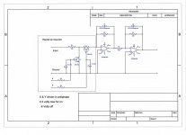
OK I have a couple more questions. I have attached a picture illustrating what I plan to do. All I want is a way to get a mono output from a stereo input, without tying the stereo signal together (to go off to a subwoofer out).
Also, is it even necessary to include the set of buffers in the centre of the schematic thing I drew? The only reason I included them is so that there would be a completely even load distribution, but now I am thinking that this doesn't even matter.
Upon studying the schematic futhur, I have realised that I stupidly shorted front left to rear left and front right to rear right permanently, within the bos which contains the opamps in question. More logic switches here I think!
An externally hosted image should be here but it was not working when we last tested it.
Last edited:
Heres an updated and simpler version of the schematic
An externally hosted image should be here but it was not working when we last tested it.
OK I have a couple more questions. I have attached a picture illustrating what I plan to do. All I want is a way to get a mono output from a stereo input, without tying the stereo signal together (to go off to a subwoofer out).
Also, is it even necessary to include the set of buffers in the centre of the schematic thing I drew? The only reason I included them is so that there would be a completely even load distribution, but now I am thinking that this doesn't even matter.
Upon studying the schematic futhur, I have realised that I stupidly shorted front left to rear left and front right to rear right permanently, within the bos which contains the opamps in question. More logic switches here I think!
An externally hosted image should be here but it was not working when we last tested it.
You need a virtual earth mixer, so that means adding 10k resistors to the output of those first opamps, then make the third an inverting stage with 10k feedback resistor. Essentially the same as in the circuit I posted earlier.
Only drawback is that inverts overall phase so you can either add another inverting stage to correct that, or make those input buffers inverting as well... easy
")
the two summing resistors go to the -IN pin, the inverting input.
The feedback also goes to this -IN pin.
The +IN pin should see the same impedance as the -IN pin to minimise output offset and offset drift with opamp temperature.
If you use three 10k resistors on your inverting summer, the -IN pin resistance is 10/3 k and the resistor load between +IN pin and Audio Ground should be ~3k3 for minimum offset and drift.
Why are you using opamps on the inputs to the pre-amp?
If the outputs of the pre-amp need buffering then the opamps should all be on the outputs not the inputs.
Good point Andrew makes about the offset problem, particularly as you are using electronic switching. Any difference in DC levels as you switch them will cause clicks and thumps in the audio.
If you use FET opamps (which I did...OP2604) there is no problem as the input currents are virtually zero (thus not developing a DC offset across the input resistances) . If you use bipolar types such as NE5532 etc then yes, it's a real issue.
If you use FET opamps (which I did...OP2604) there is no problem as the input currents are virtually zero (thus not developing a DC offset across the input resistances) . If you use bipolar types such as NE5532 etc then yes, it's a real issue.
Hows this:

Can pretty much use exactly the resistors u said as well. What would an inverting 0 gain amp circuit look like? Because I will have to invet the signal again wont I?
As for the first set of op amps, I'm just following this design - High Quality Audio Preamp
Those first op amps actually provide a gain of 6dB =]
Dan
Last edited:
read this again.the two summing resistors go to the -IN pin, the inverting input.
The feedback also goes to this -IN pin.
The point is when used as an inverting op amp, the inverting input that is connected to the input signal resistors, and the feedback loop resistor is always kept at a very low signal level (practically zero) by the feedback applied to the op amp. This VIRTUAL EARTH is what stops the input signal from one channel bleeding across to the other.
I understand. How's this -
An externally hosted image should be here but it was not working when we last tested it.
- Status
- This old topic is closed. If you want to reopen this topic, contact a moderator using the "Report Post" button.
- Home
- Source & Line
- Analog Line Level
- Building my own 10 Channel Preamp