Hi,
It's been a long time since i've reverse engineered something, yet i've never did full reversing, but just the part that took my interess.
But not today.
Today i took out the high-pass board out of oAudio 500w amp with intention to disable the boost option that is handy with sealed subs, yet makes lot of problems when you go vented (or passive radiator).
Yet, all the parts are messed-up - feedbacks, caps on opposite sides of the board, resistors placed on the basis of free space, and the last and greatest deception - The Knob Switch, which pins were shortened in opposite way:
If row1 pin1 and pin5 are shortened,
then row2 pin5 and pin4 are shortened too (weird...).
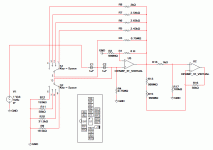
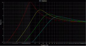
So here is the schematics, parts placement and simulation of the filter. It's Sallen-Key topology with output buffer, simple and clever.
The simulation and position of switches goes as follows:
12Hz 4,6 Red
16Hz 3,7 Yellow
20Hz 2,8 Green
25Hz 1,9 Blue
The resistor values were measured off-board, caps showed 0.99uF.
Tomorrow i'll try to play with values of resistors to get 3-6db rollof with variable frequency - for those who owns ported sub.
Attachments
- Status
- This old topic is closed. If you want to reopen this topic, contact a moderator using the "Report Post" button.

