Hi Diys,
I'm doing a high voltage high frequency oscillator for microphone experiments, however, do have a slight problem (schematic attached below).
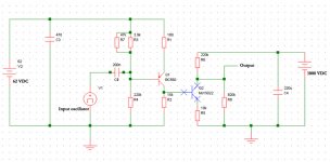
What happens is that the cutoff frequency is around 6-7 kHz and I need to be able to generate a ~ 1000 Vpp signal at around 1 MHz and with a current of app. 3 mA.
Anybody has any suggestions for a simple schematic - or improvements to the schematic below?
Thanks!
Jesper
I'm doing a high voltage high frequency oscillator for microphone experiments, however, do have a slight problem (schematic attached below).
What happens is that the cutoff frequency is around 6-7 kHz and I need to be able to generate a ~ 1000 Vpp signal at around 1 MHz and with a current of app. 3 mA.
Anybody has any suggestions for a simple schematic - or improvements to the schematic below?
Thanks!
Jesper
Attachments

Rather unclear how or why a high frequency high voltage oscillator relates to microphones?
But anyhow, buy a signal generator with the required frequency range and stability, build a high voltage amplifier to be driven by the oscillator. That would be the fastest and surest way to go without having to monkey around with it.
Building a single oscillator that will a) be stable, b) go from low audio to 1mHz without switching ranges and c) have an output in the 1000vrms range is not that simple or easy. Switched ranges and you have a shot at it. Can't say that you'll get stability without some serious work though.
_-_-bear
Your problem is that the output from your circuit is high impedance single ended, at 1Mhz it doesn't take very much shunt capacitance to kill it.
I suspect that 220K collector load when combined with Ccb and the miller effect when fed from a 15K source will comprehensively kill the gain at 1Mhz.
You really need to be applying RF techniques at these frequencies (think matching networks and RF transformers).
What impedance (not resistance) is your load? If mostly inductive or capacitive, can you make it part of a tank circuit? That way you get your voltage gain from the Q of the tank and can drive at much lower voltage wither via a tap on the inductor or via a loosely coupled primary winding of a few turns (Starts to sound like a tesla coil!).
There are some things that become very easy at RF once you start thinking in RF terms rather then audio.
Regards, Dan.
Are you mad?
Where are you getting 1000 volts of DC?
The transistor in your diagram is rated 250V.
You should think twice before messing with lethal voltages, and three times before asking stupid questions. Why on Earth would anyone want to have this signal around if they could possibly avoid it?
Unless perhaps you're intending building an AM or CW transmitter? In which case there are safer ways to develop that power output. Plus it would be illegal of course.
w
Hi!
Thanks for reading and answering
@dmills:
I will be using the circuit to find out if a "sub-plasma" microphone is feasible/possible. I.e. if high frequency conduction through air is practical for microphone purposes. Somewhat like using a plasma tweeter for a microphone but without entering the plasma state which seems to me to be noisy and also emits ozone. I reckon the impedance of the air, which is the load, will be in the range of mega ohms.
@bear: I actually do have a suitable oscillator that can go up in the MHz range. I "just" need the amplifier that can amplify the signal I usually can make my circuits stable, particularly if they are simple, so if any suggestions ???
BTW I forgot to change the transistors in the diagram - I will be using a 2SA970 for Q1 and probably a MJE18004 for Q2. Suggestions are welcome, though (for Q2 particularly).
Regards,
Jesper
Thanks for reading and answering
@dmills:
I will be using the circuit to find out if a "sub-plasma" microphone is feasible/possible. I.e. if high frequency conduction through air is practical for microphone purposes. Somewhat like using a plasma tweeter for a microphone but without entering the plasma state which seems to me to be noisy and also emits ozone. I reckon the impedance of the air, which is the load, will be in the range of mega ohms.
@bear: I actually do have a suitable oscillator that can go up in the MHz range. I "just" need the amplifier that can amplify the signal
I usually can make my circuits stable, particularly if they are simple, so if any suggestions ???BTW I forgot to change the transistors in the diagram - I will be using a 2SA970 for Q1 and probably a MJE18004 for Q2. Suggestions are welcome, though (for Q2 particularly).
Regards,
Jesper
- Status
- This old topic is closed. If you want to reopen this topic, contact a moderator using the "Report Post" button.
- Home
- Source & Line
- Analog Line Level
- High frequency high voltage oscillator - help!