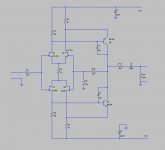
I recently purchased the JC-2 preamp kit that tubeshunter is selling on eBay. I made some changes to the stock component values to improve performance and reliablility. I also increased the gain to a little over 20 dB.
The kit I purchased did not have idss matched jfets. I had several of the JFETs on hand and selected idss matched parts. The differential pairs were matched to 0.1 mA, and the n and p channels were as close as possible. It will work without matching the fets, but the offset and distortion will be higher.
It is stable into 1000 pF capacitive loads, and has a THD of .001% in the audio band.
If you assemble this kit, be sure to test the bipolar transistors. The ones I received had their pin out reversed from the silk screen shown on the board. The picture on the eBay listing shows them inserted reversed as well.
I hope someone finds this of some use.
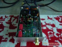
Attachments


I am glad to see amateurs making their own. I gave it to the world in 1977, after Levinson would not pay me further royalties for it. However, I am concerned when someone is making money from the design, and calling it the JC-2, because then if something goes wrong, who do you think they call first?

Thanks Mr. Curl for advice.
A friend of mine has listened to my JC-2 pre-amp. He likes it very much and wants to build one for himself but he can only get some K170V/J74V with idss matched 15ma. Is this current too much to use on this circuit? Your advice will be much appreciated.
A friend of mine has listened to my JC-2 pre-amp. He likes it very much and wants to build one for himself but he can only get some K170V/J74V with idss matched 15ma. Is this current too much to use on this circuit? Your advice will be much appreciated.
I've used these fets in this configuration in many different circuits. The idss range varies from 5.5 mA to 10.5 mA for the vast majority of the devices. Using a 56 ohm common source resistor produces a very repeatable 3 to 3.5 mA bias per device (6 to 7 mA) total. That bias will produce a tranconductance of 22 mS, and increasing the bias has a minimal effect on that gain. The 12 ohm value supplied in the tubeshunter kit runs the devices way too close to idss. My guess is that they did this to eliminate matching the devices. The original JC-2 used a potentiometer to set the device bias. Matched devices and a 56 ohm resistor eliminates the need for that pot.
I increased the drain resistance from the value in both the kit and the original circuit too. Those low values for the drain resistor operate the fets at near unity gain. There is nothing wrong with operating them near unity gain, but with a known bias current, the drain resistor can be increased which also increases the open loop gain. The known bias current also helps set the bipolar transistor operating current to approximately 30 mA. That bias increases their case temperature 30 degrees C. They are warm to the touch, but not blazing.
I increased the drain resistance from the value in both the kit and the original circuit too. Those low values for the drain resistor operate the fets at near unity gain. There is nothing wrong with operating them near unity gain, but with a known bias current, the drain resistor can be increased which also increases the open loop gain. The known bias current also helps set the bipolar transistor operating current to approximately 30 mA. That bias increases their case temperature 30 degrees C. They are warm to the touch, but not blazing.

jonusgrumby said:
The 12 ohm value supplied in the tubeshunter kit runs the devices way too close to idss.
I routinely use 10 Ohms for the 2SK389/2SJ109 or 2SK170/2SJ74.
Grey
Mr. Curl,
I'm not sure if you are joking or if you are serious.
I see no reason to roll the dice on the device operating points. In addition, my application required a higher closed loop gain, so I had to make changes. In doing so, it seemed prudent to insure that the active devices operate in their linear region and at a safe operating level.
The series output resistor will limit the maximum current to approximately 25 mA, so operating the output devices at 50 mA accomplishes nothing and only raises their operating temperature. With good airflow, this should not present a problem, but since that can not be assured, and since the higher current buys you nothing, it only makes sense to reduce it to a more reasonable level.
In my experience, the topology only takes you so far. If you want repeatable and consistant results, the circuit design has to account for the device parameters and parasitics and should not operate parts at or near their rated maximum values.
The input devices I specify (and other people have suggested) differ considerable from your original circuit. The input capacitance is higher, the transconductance is much higher, and the operating point bears analysis before making such a substitution. The original devices would have been fortunate to provide any voltage gain in the circuit. It isn't needed, the bipolar devices provide plenty of gain, so it all works fine provided the bias pot is set properly. But if these new SK and SJ higher gain devices are used, it certainly does no harm (particularly in light of the higher closed loop gain) to take advantage of their voltage gain and the favorable even order spectra it provides. With these changes, an inexperienced DIY'er can duplicate the performace and sound quality I have measured and heard.
I sincerely appreciate you taking the time to contribute to this thread. It is an honor for me to communicate with someone whose work has stood the test of time.
I'm not saying that 10 or 12 ohms won't work, it will. Your input circuit will be biased at a level much more closely tied to the idss of the jfets. That will vary the voltage drop across the drain resistor and the bias of your output devices. You now have two unknowns.
Increasing the value to 56 ohms will set that bias current to 3 mA per device +/- 0.5 mA. It also sets the output bias to approximately 30 mA, which operated the device junctions at a much lower temperature.
Increasing the value to 56 ohms will set that bias current to 3 mA per device +/- 0.5 mA. It also sets the output bias to approximately 30 mA, which operated the device junctions at a much lower temperature.
- Home
- Source & Line
- Analog Line Level
- Variation on the JC-2 preamplifier