CG, your discussion is most insightful and helpful to everyone. I am a mechanical engineer in trade (retired). Is it possible to share your LTSPICE simulation files?Thanks very much - you're most kind.
You may be the only one who cares, but I thought I should post my results as a kind of closure for this preamp project. Even if it is years after the fact.
How do you do measurements at home with a Peak DCA-75, an Analog Discovery 2, and a QuantAsylum QA-401. It is probably all above my head, but will be very interesting to read.
... But, now, I could make all the same measurements at home with a Peak DCA-75, an Analog Discovery 2, and a QuantAsylum QA-401. I could even easily measure the closed loop gain and phase margin, too. That's real progress on the DIY front.
That's most interesting: Scott Wurcer just did a post about the Analog Discovery 2 here. I'd like to know more.
... It is probably all above my head, but will be very interesting to read.
Don't discredit yourself: one of the most incredible talk I've attended was at an AES convention by a guy called Clifford A. Henricksen. He used to work for Altec when Altec was still doing commendable stuff, and invented and patented the "Manta Ray Horn". Because he's a mechanical engineer, his equivalent circuits are entirely made of gears, levers, springs, pivots, and so on!
The Analog Discovery (now version 2) is kind of a universal lab gadget. I think the original purpose of the product was to offer lab gear that an engineering student could use for investigating what she or he was studying in class. It's based around some devices from Analog Devices and an FPGA that is programmed to perform loads of functions when connected to a computer through a USB port. That's the summary. For more information, look here:
USB Oscilloscope and Logic Analyzer - Digilent Analog Discovery 2
Be sure to check out the probes at the bottom of the page as well as the attachments, like the impedance analyzer.
The Analog Discovery 2 can be used as an oscilloscope, a test generator, a spectrum analyzer, and a host of other tools. So, you can make measurements of transient response for an amplifier, look for out of band garbage, and on and on.
A number of clever people have devised ways to use the AD2 as curve tracer. In addition to the Scott Wurcer example of the curve tracer, here's another:
https://www.instructables.com/id/Semiconductor-Curve-Tracer-With-the-Analog-Discove/
Want to measure loop gain and phase?
Activity: Measuring Loop Gain [Analog Devices Wiki]
Is this equivalent to a rack full of Tektronix and Keysight gear? NO!
Good enough for home experimentation? You decide.
Since I don't use gear like this at home every day, I especially appreciate that it does so much in such a small package. (Using a computer for much of the heavy lifting is a big part of that.)
There's already a thread on the QA401 on this web site, so I'll skip that.
The DCA75 is a semiconductor curve tracer I bought before I even heard of the AD2.
Peak Atlas DCA Pro model DCA75 | Peak Electronic Design Limited
Because of its design, I find it to be much easier to use when sorting devices than the curve tracing function of the AD2.
My own goal is to have a wide range of test and experimentation capability that only takes up a single shelf in a closet in the spare bedroom where the work table is. I think with this and some other gear, I can do more than most audio labs could do back in the 90's and before. That's when most analog audio gear was designed. Much since has just been refinement of those basic ideas. (Obviously, digital audio and Class-D amplifiers are an exception.). I'm not trivializing what has come since, but let's face it - there haven't been many new semiconductors introduced for analog audio use since that time. In fact, many parts we all like have been discontinued.
Is it possible to share your LTSPICE simulation files?
I will put this together. Be careful what you ask for!
Here is a zip bundle, as promised.
There's some things you probably need to do.
First, if you don't have Bob Cordell's book on amplifiers, I'd really recommend it. The chapters devoted to using LTSPICE are worth the price by themselves.
CordellAudio.com - Designing Audio Power Amplifiers
Second, you might not have the SPICE models for the semiconductors. I've put those into a text file named Spice Models.txt (not copyright...) You can either add them to the standard LTSPICE amp libraries (that's what I did, so I can use them in other designs) or just add them to each .asc file. This is described in Cordell's book.
Third, the margin simulation is based on the Tian method, as described by Frank Wiedmann here:
Loop Gain Simulation - Frank Wiedmann
There's a couple things you need to add to your LTSPICE installation to make that all work. It's a one time proposition, though.
The three basic designs are the original JC-2 Clone (NOT the original JC-2), the "fixed" JC-2 Clone, and the version I came up with (JC2-10). You can decide which one you like best.
The distortion simulations have taken into account all the little details Bob Cordell describes having to do with proper use of the FFT within LTSPICE and so on. Personally, I like figuring these things out only once, so I use variables and sorta English expressions to force LTSPICE to calculate parameters that make it all work right. Let the computer do the work. Then, I reuse that simulation scheme over and over. More recently I changed the scheme so that I could simulate IMD with multiple tones more easily. The old scheme here works just fine for simple harmonic distortion.
Attachments
It is amazing how analogue instrument has evolved. Does the AD2 have enough resolution to measure noise in the spectrum analyzer mode?The Analog Discovery (now version 2) is kind of a universal lab gadget. I think the original purpose of the product was to offer lab gear that an engineering student could use for investigating what she or he was studying in class. It's based around some devices from Analog Devices and an FPGA that is programmed to perform loads of functions when connected to a computer through a USB port. That's the summary. For more information, look here:
USB Oscilloscope and Logic Analyzer - Digilent Analog Discovery 2
Be sure to check out the probes at the bottom of the page as well as the attachments, like the impedance analyzer.
The Analog Discovery 2 can be used as an oscilloscope, a test generator, a spectrum analyzer, and a host of other tools. So, you can make measurements of transient response for an amplifier, look for out of band garbage, and on and on.
A number of clever people have devised ways to use the AD2 as curve tracer. In addition to the Scott Wurcer example of the curve tracer, here's another:
https://www.instructables.com/id/Semiconductor-Curve-Tracer-With-the-Analog-Discove/
Want to measure loop gain and phase?
Activity: Measuring Loop Gain [Analog Devices Wiki]
Is this equivalent to a rack full of Tektronix and Keysight gear? NO!
Good enough for home experimentation? You decide.
Since I don't use gear like this at home every day, I especially appreciate that it does so much in such a small package. (Using a computer for much of the heavy lifting is a big part of that.)
There's already a thread on the QA401 on this web site, so I'll skip that.
The DCA75 is a semiconductor curve tracer I bought before I even heard of the AD2.
Peak Atlas DCA Pro model DCA75 | Peak Electronic Design Limited
Because of its design, I find it to be much easier to use when sorting devices than the curve tracing function of the AD2.
My own goal is to have a wide range of test and experimentation capability that only takes up a single shelf in a closet in the spare bedroom where the work table is. I think with this and some other gear, I can do more than most audio labs could do back in the 90's and before. That's when most analog audio gear was designed. Much since has just been refinement of those basic ideas. (Obviously, digital audio and Class-D amplifiers are an exception.). I'm not trivializing what has come since, but let's face it - there haven't been many new semiconductors introduced for analog audio use since that time. In fact, many parts we all like have been discontinued.
I have not had access to a semiconductor curve tracer since I left graduate school 40 years ago. For the $127 price at Newark, the DCA75 is an excellent device for people who wants to match jFET for the JC-2 front end. I have the TC1 multifunction tester which does more test than the Peak DCA55, but has no output for curve tracing. The TC1 is a good tool for quick sorting of transistor.
It is amazing how analogue instrument has evolved. Does the AD2 have enough resolution to measure noise in the spectrum analyzer mode?
That, ahh, depends.
If you just want to measure noise, with no signal present, you can use a preamp to get wherever you want. It’s a matter of the noise figure and gain of the preamp.
The QA401 has more sensitivity, but even it can often require some external gain. QuantAsylum has the QA470 for that, if you don’t want to build your own.
Characterizing LDO Noise: Part 3
– QuantAsylum
Again, I have no connection to any of these companies. I have to buy it all at retail or occasional sales prices, like most everybody else here.
Yup - dead.
Out of curiosity, I simulated using some currently available, in production semiconductors for this design.
It certainly looks to me like using Linear LSK489's and LSJ689's at the input with KSA1381's and KSC3503DS's in the VAS stage should work well. Between 4 and 5 mA per input JFET and 22 pF for the Miller compensation caps seems to be pretty good.
The bandwidth is about a MHz or so, and the feedback loop gain is almost constant to above 40 KHz - down about 3 dB at 70 KHz or so. The noise is pretty low, too.
If you add a servo based around one of the newer TI JFET input opamps, you spare yourself from adjusting a pot and the DC offset at the output stays constant over temperature and time.
Despite its age and simplicity, this is still a great circuit that is hard to beat.
Last edited:
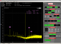
Today I was trying out my new QuantAsylum QA480 that goes along with my QA401. This is a low distortion 1 KHz analog oscillator combined with a notch filter. It's computer controlled, and along with the software now in the QA401, I can measure down to a distortion level of about -150 dB. That's the second harmonic level from the oscillator itself. Only at 1 KHz, but I'm not going to complain. Imagine being able to measure distortion that low with a tiny box that attaches to the USB ports of a computer for way less than $1k.
So, I measured the JC-2 I updated as described earlier. 2SJ103's and 2SK246's at the input and 2SC3468's and 2SA1381's at the output.
The distortion plots are below.
What's amazing, to me anyway, is that the LTSPICE simulation gave:
1 Vrms 2 Vrms
2nd -106 -99
3rd -128 -118
(Sorry for the lousy formatting)
The simulation agrees with the measurement within a dB or two. I guess simulation does work pretty well after all.
The big trouble makers are from the power transformer and the rectifier harmonics.
Attachments
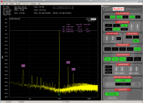
Today I was trying out my new QuantAsylum QA480 that goes along with my QA401. This is a low distortion 1 KHz analog oscillator combined with a notch filter. It's computer controlled, and along with the software now in the QA401, I can measure down to a distortion level of about -150 dB. That's the second harmonic level from the oscillator itself. Only at 1 KHz, but I'm not going to complain. Imagine being able to measure distortion that low with a tiny box that attaches to the USB ports of a computer for way less than $1k.
So, I measured the JC-2 I updated as described earlier. 2SJ103's and 2SK246's at the input and 2SC3468's and 2SA1381's at the output.
The distortion plots are below.
What's amazing, to me anyway, is that the LTSPICE simulation gave:
1 Vrms 2 Vrms
2nd -106 -99
3rd -128 -118
(Sorry for the lousy formatting)
The simulation agrees with the measurement within a dB or two. I guess simulation does work pretty well after all.
The big trouble makers are from the power transformer and the rectifier harmonics.
Attachments
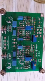
Here's my Ebay chinese JC-2 inspired pre which I have tuned ") .
.
-Dale RS res (0,5/0,1% tolerance C and E series, non-magnetic)
-Epcos LL lytics
-Silver mica pf caps
-SiC schottky diodes + trafo sec. RC-damping
-Made the pre DC-connected by removing output caps and feedback loop cap that made the feedback AC
-Put the potentiometer from the input to output and changed to motorized pot
-After simming in LTspice removed the emitter follower output buffer transistors, now the schematic is +/- like JC-2.
Transistors in this chinese version are 2SK170/2SJ74 and 2SB647/2SD667. They seem to be well matched, DC offset is 3-5mV pot turned fully open (pot at output attenuates it also). I didnt even install dc-offset trimmer resistor.
This is a very fine sounding pre and I'm amazed how simple and compact the signal path of the JC-2 is.
I cannot explain why, since the load is referenced to earth and not floating, but by putting a "rail-to-rail" (between +15V and -15V) polyprop capacitor max locally around the output stage makes the sound noticeably better.

. -Dale RS res (0,5/0,1% tolerance C and E series, non-magnetic)
-Epcos LL lytics
-Silver mica pf caps
-SiC schottky diodes + trafo sec. RC-damping
-Made the pre DC-connected by removing output caps and feedback loop cap that made the feedback AC
-Put the potentiometer from the input to output and changed to motorized pot
-After simming in LTspice removed the emitter follower output buffer transistors, now the schematic is +/- like JC-2.
Transistors in this chinese version are 2SK170/2SJ74 and 2SB647/2SD667. They seem to be well matched, DC offset is 3-5mV pot turned fully open (pot at output attenuates it also). I didnt even install dc-offset trimmer resistor.
This is a very fine sounding pre and I'm amazed how simple and compact the signal path of the JC-2 is.
I cannot explain why, since the load is referenced to earth and not floating, but by putting a "rail-to-rail" (between +15V and -15V) polyprop capacitor max locally around the output stage makes the sound noticeably better.
Last edited:
Good question! I have found the output pot to be quite a no brainer. IMO so much better than conventional way where to put it, ie. at the input.
I have Goldmund Mimesis variation amps (2sk170 jfet input also) which have high gain + horn speakers.
The basic hiss of the system becomes ink black with pot at output. Low resistance from the wiper to ground almost shorts the input of the amp plus the pot attenuates hiss from pre and dac/riaa.
Amps by themselves without anything connected to them or DAC directly connected to amps results hiss that can be heard. Pre with output pot connected to amps and the system does not give any indication if the amps are on or off even right at the horn, it's very silent. Hiss gets gradually louder as I turn the pot open.
The SNR of the dac+pre is also at their maximum since both of them are constantly at "max volume" when playing music.
Output impedance of the 10k pot (and 22k res across it) is around 250-500ohm (pot at clock 10) when I have turned the pot to loudest 110dB+ levels I ever listen, it's quite negligible. At maximum the output impedance is couple of kilo ohms depending where the pot faces, if some super low gain/unity gain amps are used and I would need to turn the pot to max (6-9Vrms output approx).
Also there is more voltage and current across the pot at the output, it operates more transparent perhaps (at least sounds much better but it depends on many things).
Output pot also attenuates the DC offset of the pre and DAC for the DC-connected amps. I have fully DC connected signal path without servos and the amps DC-offset is basically the same than when their input is shorted/unconnected.
Last edited:
- Home
- Source & Line
- Analog Line Level
- Variation on the JC-2 preamplifier